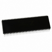
Z8018010PSG Zilog, Z8018010PSG Datasheet - Page 139

Z8018010PSG
Manufacturer Part Number
Z8018010PSG
Description
IC 10MHZ Z180 CMOS ENH MPU 64DIP
Manufacturer
Zilog
Specifications of Z8018010PSG
Processor Type
Z180
Features
8-Bit, Enhanced Z80 Megacell
Speed
10MHz
Voltage
5V
Mounting Type
Through Hole
Package / Case
64-DIP (0.750", 19.05mm)
Processor Series
Z8018xx
Core
Z80
Data Bus Width
8 bit
Maximum Clock Frequency
10 MHz
Number Of Timers
2
Operating Supply Voltage
0 V to 5 V
Maximum Operating Temperature
+ 70 C
Mounting Style
Through Hole
Minimum Operating Temperature
0 C
Core Size
8bit
Cpu Speed
10MHz
Digital Ic Case Style
DIP
No. Of Pins
64
Supply Voltage Range
4.5V To 5.5V
Operating Temperature Range
0°C To +70°C
Svhc
No SVHC (18-Jun-2010)
Base Number
8018010
Rohs Compliant
Yes
Clock Frequency
10MHz
Lead Free Status / RoHS Status
Lead free / RoHS Compliant
Other names
269-3889
Z8018010PSG
Z8018010PSG
Available stocks
Company
Part Number
Manufacturer
Quantity
Price
Company:
Part Number:
Z8018010PSG
Manufacturer:
Zilog
Quantity:
40
- Current page: 139 of 326
- Download datasheet (5Mb)
124
UM005003-0703
Bit
Position Bit/Field R/W
4
3
2
1
0
Z8018x
Family MPU User Manual
FE
RIE
CTS1E
TDRE
TIE
R
R/W
R/W
R
R/W
Value
Description
Framing Error — If a receive data byte frame is
delimited by an invalid stop bit (that is, 0, should be 1),
FE is set to 1. FE is cleared to 0 when the EFR bit (Error
Flag Reset) of CNTLA is written to 0, when DCD0 is
High, in IOSTOP mode, and during RESET.
Receive Interrupt Enable — RIE must be set to 1 to
enable ASCI receive interrupt requests. When RIE is 1, if
any of the flags RDRF, OVRN, PE, or FE become set to
1, an interrupt request is generated. For channel 0, an
interrupt is also generated by the transition of the external
DCD0 input from Low to High.
Channel 1 CTS Enable — Channel 1 has an external
CTS1 input which is multiplexed with the receive data
pin (RXS) for the CSI/O (Clocked Serial I/O Port).
Setting CTS1E to 1 selects the CTS1 function and
clearing CTS1E to 0 selects the RXS function.
Transmit Data Register Empty — TDRE = 1 indicates
that the TDR is empty and the next transmit data byte is
written to TDR. After the byte is written to TDR, TDRE
is cleared to 0 until the ASCI transfers the byte from TDR
to the TSR and then TDRE is again set to 1. TDRE is set
to 1 in IOSTOP mode and during RESET. When the
external CTS input is High, TDRE is reset to 0.
Transmit Interrupt Enable — TIE must be set to 1 to
enable ASCI transmit interrupt requests. If TIE is 1, an
interrupt is requested when TDRE is 1. TIE is cleared to 0
during RESET.
Related parts for Z8018010PSG
Image
Part Number
Description
Manufacturer
Datasheet
Request
R

Part Number:
Description:
Microprocessor Unit
Manufacturer:
ZiLOG Semiconductor
Datasheet:

Part Number:
Description:
Z80180 EMULATOR
Manufacturer:
Zilog
Datasheet:

Part Number:
Description:
Z80180, Z8s180, Z8l180 Mpu Operation
Manufacturer:
ZiLOG Semiconductor
Datasheet:

Part Number:
Description:
Communication Controllers, ZILOG INTELLIGENT PERIPHERAL CONTROLLER (ZIP)
Manufacturer:
Zilog, Inc.
Datasheet:

Part Number:
Description:
KIT DEV FOR Z8 ENCORE 16K TO 64K
Manufacturer:
Zilog
Datasheet:

Part Number:
Description:
KIT DEV Z8 ENCORE XP 28-PIN
Manufacturer:
Zilog
Datasheet:

Part Number:
Description:
DEV KIT FOR Z8 ENCORE 8K/4K
Manufacturer:
Zilog
Datasheet:

Part Number:
Description:
KIT DEV Z8 ENCORE XP 28-PIN
Manufacturer:
Zilog
Datasheet:

Part Number:
Description:
DEV KIT FOR Z8 ENCORE 4K TO 8K
Manufacturer:
Zilog
Datasheet:

Part Number:
Description:
CMOS Z8 microcontroller. ROM 16 Kbytes, RAM 256 bytes, speed 16 MHz, 32 lines I/O, 3.0V to 5.5V
Manufacturer:
Zilog, Inc.
Datasheet:

Part Number:
Description:
Low-cost microcontroller. 512 bytes ROM, 61 bytes RAM, 8 MHz
Manufacturer:
Zilog, Inc.
Datasheet:

Part Number:
Description:
Z8 4K OTP Microcontroller
Manufacturer:
Zilog, Inc.
Datasheet:

Part Number:
Description:
CMOS SUPER8 ROMLESS MCU
Manufacturer:
Zilog, Inc.
Datasheet:

Part Number:
Description:
SL1866 CMOSZ8 OTP Microcontroller
Manufacturer:
Zilog, Inc.
Datasheet:


