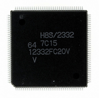
D12332VFC20V Renesas Electronics America, D12332VFC20V Datasheet - Page 29

D12332VFC20V
Manufacturer Part Number
D12332VFC20V
Description
IC H8S/2332 MCU ROMLESS 144QFP
Manufacturer
Renesas Electronics America
Series
H8® H8S/2300r
Specifications of D12332VFC20V
Core Processor
H8S/2000
Core Size
16-Bit
Speed
20MHz
Connectivity
SCI, SmartCard
Peripherals
DMA, POR, PWM, WDT
Number Of I /o
106
Program Memory Type
ROMless
Ram Size
8K x 8
Voltage - Supply (vcc/vdd)
2.7 V ~ 3.6 V
Data Converters
A/D 12x10b; D/A 4x8b
Oscillator Type
Internal
Operating Temperature
-20°C ~ 75°C
Package / Case
144-QFP
For Use With
EDK2329 - DEV EVALUATION KIT H8S/2329
Lead Free Status / RoHS Status
Lead free / RoHS Compliant
Eeprom Size
-
Program Memory Size
-
Available stocks
Company
Part Number
Manufacturer
Quantity
Price
Company:
Part Number:
D12332VFC20V
Manufacturer:
Renesas Electronics America
Quantity:
10 000
- Current page: 29 of 1246
- Download datasheet (7Mb)
19.21 Flash Memory Programming and Erasing Precautions ..................................................... 841
Section 20 Clock Pulse Generator
20.1 Overview........................................................................................................................... 847
20.2 Register Descriptions ........................................................................................................ 848
20.3 Oscillator........................................................................................................................... 850
20.4 Duty Adjustment Circuit................................................................................................... 854
20.5 Medium-Speed Clock Divider .......................................................................................... 854
20.6 Bus Master Clock Selection Circuit .................................................................................. 854
Section 21 Power-Down Modes
21.1 Overview........................................................................................................................... 855
21.2 Register Descriptions ........................................................................................................ 857
21.3 Medium-Speed Mode........................................................................................................ 861
21.4 Sleep Mode ....................................................................................................................... 862
21.5 Module Stop Mode............................................................................................................ 863
21.6 Software Standby Mode.................................................................................................... 865
21.7 Hardware Standby Mode .................................................................................................. 868
21.8 φ Clock Output Disabling Function .................................................................................. 869
20.1.1 Block Diagram..................................................................................................... 847
20.1.2 Register Configuration......................................................................................... 848
20.2.1 System Clock Control Register (SCKCR) ........................................................... 848
20.3.1 Connecting a Crystal Resonator........................................................................... 850
20.3.2 External Clock Input ............................................................................................ 852
21.1.1 Register Configuration......................................................................................... 856
21.2.1 Standby Control Register (SBYCR) .................................................................... 857
21.2.2 System Clock Control Register (SCKCR) ........................................................... 859
21.2.3 Module Stop Control Register (MSTPCR) .......................................................... 861
21.5.1 Module Stop Mode .............................................................................................. 863
21.5.2 Usage Notes ......................................................................................................... 864
21.6.1 Software Standby Mode....................................................................................... 865
21.6.2 Clearing Software Standby Mode ........................................................................ 865
21.6.3 Setting Oscillation Stabilization Time after Clearing Software Standby Mode... 866
21.6.4 Software Standby Mode Application Example.................................................... 866
21.6.5 Usage Notes ......................................................................................................... 867
21.7.1 Hardware Standby Mode ..................................................................................... 868
21.7.2 Hardware Standby Mode Timing......................................................................... 868
...................................................................................... 855
.................................................................................. 847
Rev.4.00 Sep. 07, 2007 Page xxvii of xxx
Related parts for D12332VFC20V
Image
Part Number
Description
Manufacturer
Datasheet
Request
R

Part Number:
Description:
KIT STARTER FOR M16C/29
Manufacturer:
Renesas Electronics America
Datasheet:

Part Number:
Description:
KIT STARTER FOR R8C/2D
Manufacturer:
Renesas Electronics America
Datasheet:

Part Number:
Description:
R0K33062P STARTER KIT
Manufacturer:
Renesas Electronics America
Datasheet:

Part Number:
Description:
KIT STARTER FOR R8C/23 E8A
Manufacturer:
Renesas Electronics America
Datasheet:

Part Number:
Description:
KIT STARTER FOR R8C/25
Manufacturer:
Renesas Electronics America
Datasheet:

Part Number:
Description:
KIT STARTER H8S2456 SHARPE DSPLY
Manufacturer:
Renesas Electronics America
Datasheet:

Part Number:
Description:
KIT STARTER FOR R8C38C
Manufacturer:
Renesas Electronics America
Datasheet:

Part Number:
Description:
KIT STARTER FOR R8C35C
Manufacturer:
Renesas Electronics America
Datasheet:

Part Number:
Description:
KIT STARTER FOR R8CL3AC+LCD APPS
Manufacturer:
Renesas Electronics America
Datasheet:

Part Number:
Description:
KIT STARTER FOR RX610
Manufacturer:
Renesas Electronics America
Datasheet:

Part Number:
Description:
KIT STARTER FOR R32C/118
Manufacturer:
Renesas Electronics America
Datasheet:

Part Number:
Description:
KIT DEV RSK-R8C/26-29
Manufacturer:
Renesas Electronics America
Datasheet:

Part Number:
Description:
KIT STARTER FOR SH7124
Manufacturer:
Renesas Electronics America
Datasheet:

Part Number:
Description:
KIT STARTER FOR H8SX/1622
Manufacturer:
Renesas Electronics America
Datasheet:

Part Number:
Description:
KIT DEV FOR SH7203
Manufacturer:
Renesas Electronics America
Datasheet:


