D12332VFC20V Renesas Electronics America, D12332VFC20V Datasheet - Page 844
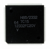
D12332VFC20V
Manufacturer Part Number
D12332VFC20V
Description
IC H8S/2332 MCU ROMLESS 144QFP
Manufacturer
Renesas Electronics America
Series
H8® H8S/2300r
Specifications of D12332VFC20V
Core Processor
H8S/2000
Core Size
16-Bit
Speed
20MHz
Connectivity
SCI, SmartCard
Peripherals
DMA, POR, PWM, WDT
Number Of I /o
106
Program Memory Type
ROMless
Ram Size
8K x 8
Voltage - Supply (vcc/vdd)
2.7 V ~ 3.6 V
Data Converters
A/D 12x10b; D/A 4x8b
Oscillator Type
Internal
Operating Temperature
-20°C ~ 75°C
Package / Case
144-QFP
For Use With
EDK2329 - DEV EVALUATION KIT H8S/2329
Lead Free Status / RoHS Status
Lead free / RoHS Compliant
Eeprom Size
-
Program Memory Size
-
Available stocks
Company
Part Number
Manufacturer
Quantity
Price
Company:

Part Number:
D12332VFC20V
Manufacturer:
Renesas Electronics America
Quantity:
10 000


• Before branching to the programming control program (RAM area H'FFE400 to H'FFFBFF),
• Boot mode can be entered by making the pin settings shown in table 19.30 and executing a
• If the mode pin input levels are changed (for example, from low to high) during a reset, the
Notes: 1. Mode pins and FWE pin input must satisfy the mode programming setup time (t
Rev.4.00 Sep. 07, 2007 Page 812 of 1210
REJ09B0245-0400
the chip terminates transmit and receive operations by the on-chip SCI (channel 1) (by clearing
the RE and TE bits in SCR to 0), but the adjusted bit rate value remains set in BRR. The
transmit data output pin, TxD1, goes to the high-level output state (P31DDR = 1, P31DR = 1).
The contents of the CPU’s internal general registers are undefined at this time, so these
registers must be initialized immediately after branching to the programming control program.
In particular, since the stack pointer (SP) is used implicitly in subroutine calls, etc., a stack area
must be specified for use by the programming control program.
Initial settings must also be made for the other on-chip registers.
reset-start.
Boot mode can be cleared by driving the reset pin low, waiting at least 20 states, then setting
the FWE pin and mode pins, and executing reset release *
WDT overflow reset.
Do not change the mode pin input levels in boot mode, and do not drive the FWE pin low
while the boot program is being executed or while flash memory is being programmed or
erased *
state of ports with multiplexed address functions and bus control output pins (AS, RD, HWR)
will change according to the change in the microcomputer’s operating mode *
Therefore, care must be taken to make pin settings to prevent these pins from becoming output
signal pins during a reset, or to prevent collision with signals outside the microcomputer.
2. For further information on FWE application and disconnection, see section 19.21,
3. See section 9, I/O Ports.
2
200 ns) with respect to the reset release timing, as shown in figures 19.56 to 19.58.
Flash Memory Programming and Erasing Precautions.
.
1
. Boot mode can also be cleared by a
3
.
MDS
=
Related parts for D12332VFC20V
Image
Part Number
Description
Manufacturer
Datasheet
Request
R

Part Number:
Description:
KIT STARTER FOR M16C/29
Manufacturer:
Renesas Electronics America
Datasheet:

Part Number:
Description:
KIT STARTER FOR R8C/2D
Manufacturer:
Renesas Electronics America
Datasheet:

Part Number:
Description:
R0K33062P STARTER KIT
Manufacturer:
Renesas Electronics America
Datasheet:

Part Number:
Description:
KIT STARTER FOR R8C/23 E8A
Manufacturer:
Renesas Electronics America
Datasheet:

Part Number:
Description:
KIT STARTER FOR R8C/25
Manufacturer:
Renesas Electronics America
Datasheet:

Part Number:
Description:
KIT STARTER H8S2456 SHARPE DSPLY
Manufacturer:
Renesas Electronics America
Datasheet:

Part Number:
Description:
KIT STARTER FOR R8C38C
Manufacturer:
Renesas Electronics America
Datasheet:

Part Number:
Description:
KIT STARTER FOR R8C35C
Manufacturer:
Renesas Electronics America
Datasheet:

Part Number:
Description:
KIT STARTER FOR R8CL3AC+LCD APPS
Manufacturer:
Renesas Electronics America
Datasheet:
Part Number:
Description:
KIT STARTER FOR RX610
Manufacturer:
Renesas Electronics America
Datasheet:

Part Number:
Description:
KIT STARTER FOR R32C/118
Manufacturer:
Renesas Electronics America
Datasheet:

Part Number:
Description:
KIT DEV RSK-R8C/26-29
Manufacturer:
Renesas Electronics America
Datasheet:

Part Number:
Description:
KIT STARTER FOR SH7124
Manufacturer:
Renesas Electronics America
Datasheet:

Part Number:
Description:
KIT STARTER FOR H8SX/1622
Manufacturer:
Renesas Electronics America
Datasheet:

Part Number:
Description:
KIT DEV FOR SH7203
Manufacturer:
Renesas Electronics America
Datasheet: