D12332VFC20V Renesas Electronics America, D12332VFC20V Datasheet - Page 97
D12332VFC20V
Manufacturer Part Number
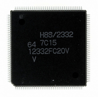
D12332VFC20V
Description
IC H8S/2332 MCU ROMLESS 144QFP
Manufacturer
Renesas Electronics America
Series
H8® H8S/2300r
Specifications of D12332VFC20V
Core Processor
H8S/2000
Core Size
16-Bit
Speed
20MHz
Connectivity
SCI, SmartCard
Peripherals
DMA, POR, PWM, WDT
Number Of I /o
106
Program Memory Type
ROMless
Ram Size
8K x 8
Voltage - Supply (vcc/vdd)
2.7 V ~ 3.6 V
Data Converters
A/D 12x10b; D/A 4x8b
Oscillator Type
Internal
Operating Temperature
-20°C ~ 75°C
Package / Case
144-QFP
For Use With
EDK2329 - DEV EVALUATION KIT H8S/2329
Lead Free Status / RoHS Status
Lead free / RoHS Compliant
Eeprom Size
-
Program Memory Size
-
Available stocks
Company
Part Number
Manufacturer
Quantity
Price
Company:

Part Number:
D12332VFC20V
Manufacturer:
Renesas Electronics America
Quantity:
10 000


2.8.6
The power-down state includes both modes in which the CPU stops operating and modes in which
the CPU does not stop. There are three modes in which the CPU stops operating: sleep mode,
software standby mode, and hardware standby mode. There are also two other power-down
modes: medium-speed mode, and module stop mode. In medium-speed mode the CPU and other
bus masters operate on a medium-speed clock. Module stop mode permits halting of the operation
of individual modules, other than the CPU. For details, refer to section 21, Power-Down Modes.
(1) Sleep Mode: A transition to sleep mode is made if the SLEEP instruction is executed while
the software standby bit (SSBY) in the standby control register (SBYCR) is cleared to 0. In sleep
mode, CPU operations stop immediately after execution of the SLEEP instruction. The contents of
CPU registers are retained.
(2) Software Standby Mode: A transition to software standby mode is made if the SLEEP
instruction is executed while the SSBY bit in SBYCR is set to 1. In software standby mode, the
CPU and clock halt and all MCU operations stop. As long as a specified voltage is supplied, the
contents of CPU registers and on-chip RAM are retained. The I/O ports also remain in their
existing states.
(3) Hardware Standby Mode: A transition to hardware standby mode is made when the STBY
pin goes low. In hardware standby mode, the CPU and clock halt and all MCU operations stop.
The on-chip supporting modules are reset, but as long as a specified voltage is supplied, on-chip
RAM contents are retained.
2.9
2.9.1
The CPU is driven by a system clock, denoted by the symbol φ. The period from one rising edge
of φ to the next is referred to as a "state." The memory cycle or bus cycle consists of one, two, or
three states. Different methods are used to access on-chip memory, on-chip supporting modules,
and the external address space.
2.9.2
On-chip memory is accessed in one state. The data bus is 16 bits wide, permitting both byte and
word transfer instruction. Figure 2.14 shows the on-chip memory access cycle. Figure 2.15 shows
the pin states.
Power-Down State
Basic Timing
Overview
On-Chip Memory (ROM, RAM)
Rev.4.00 Sep. 07, 2007 Page 65 of 1210
REJ09B0245-0400
Related parts for D12332VFC20V
Image
Part Number
Description
Manufacturer
Datasheet
Request
R

Part Number:
Description:
KIT STARTER FOR M16C/29
Manufacturer:
Renesas Electronics America
Datasheet:

Part Number:
Description:
KIT STARTER FOR R8C/2D
Manufacturer:
Renesas Electronics America
Datasheet:

Part Number:
Description:
R0K33062P STARTER KIT
Manufacturer:
Renesas Electronics America
Datasheet:

Part Number:
Description:
KIT STARTER FOR R8C/23 E8A
Manufacturer:
Renesas Electronics America
Datasheet:

Part Number:
Description:
KIT STARTER FOR R8C/25
Manufacturer:
Renesas Electronics America
Datasheet:

Part Number:
Description:
KIT STARTER H8S2456 SHARPE DSPLY
Manufacturer:
Renesas Electronics America
Datasheet:

Part Number:
Description:
KIT STARTER FOR R8C38C
Manufacturer:
Renesas Electronics America
Datasheet:

Part Number:
Description:
KIT STARTER FOR R8C35C
Manufacturer:
Renesas Electronics America
Datasheet:

Part Number:
Description:
KIT STARTER FOR R8CL3AC+LCD APPS
Manufacturer:
Renesas Electronics America
Datasheet:
Part Number:
Description:
KIT STARTER FOR RX610
Manufacturer:
Renesas Electronics America
Datasheet:

Part Number:
Description:
KIT STARTER FOR R32C/118
Manufacturer:
Renesas Electronics America
Datasheet:

Part Number:
Description:
KIT DEV RSK-R8C/26-29
Manufacturer:
Renesas Electronics America
Datasheet:

Part Number:
Description:
KIT STARTER FOR SH7124
Manufacturer:
Renesas Electronics America
Datasheet:

Part Number:
Description:
KIT STARTER FOR H8SX/1622
Manufacturer:
Renesas Electronics America
Datasheet:

Part Number:
Description:
KIT DEV FOR SH7203
Manufacturer:
Renesas Electronics America
Datasheet: