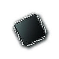
PIC18F87J72-I/PT Microchip Technology, PIC18F87J72-I/PT Datasheet - Page 175

PIC18F87J72-I/PT
Manufacturer Part Number
PIC18F87J72-I/PT
Description
IC PIC MCU 8BIT 14KB FLSH 80TQFP
Manufacturer
Microchip Technology
Series
PIC® 18Fr
Datasheet
1.PIC18F86J72-IPT.pdf
(480 pages)
Specifications of PIC18F87J72-I/PT
Program Memory Type
FLASH
Program Memory Size
128KB (64K x 16)
Package / Case
80-TQFP
Core Processor
PIC
Core Size
8-Bit
Speed
48MHz
Connectivity
I²C, LIN, SPI, UART/USART
Peripherals
Brown-out Detect/Reset, LCD, LVD, POR, PWM, WDT
Number Of I /o
51
Ram Size
3.8K x 8
Voltage - Supply (vcc/vdd)
2 V ~ 3.6 V
Data Converters
A/D 12x12b
Oscillator Type
Internal
Operating Temperature
-40°C ~ 85°C
Data Bus Width
8 bit
Data Ram Size
4 KB
Interface Type
SPI, USART, SPI, I2C
Maximum Clock Frequency
8 MHz
Number Of Programmable I/os
51
Number Of Timers
4
Operating Supply Voltage
2 V to 3.6 V
Maximum Operating Temperature
+ 85 C
Mounting Style
SMD/SMT
Minimum Operating Temperature
- 40 C
On-chip Adc
14
Controller Family/series
PIC18F
No. Of I/o's
51
Ram Memory Size
3923Byte
Cpu Speed
48MHz
No. Of Timers
4
Rohs Compliant
Yes
Lead Free Status / RoHS Status
Lead free / RoHS Compliant
Lead Free Status / RoHS Status
Lead free / RoHS Compliant, Lead free / RoHS Compliant
Available stocks
Company
Part Number
Manufacturer
Quantity
Price
Company:
Part Number:
PIC18F87J72-I/PT
Manufacturer:
Microchip
Quantity:
210
Company:
Part Number:
PIC18F87J72-I/PT
Manufacturer:
Microchip Technology
Quantity:
10 000
- Current page: 175 of 480
- Download datasheet (5Mb)
17.3.3.3
M2 operation also uses the LCD regulator but disables
the charge pump. The regulator’s internal voltage refer-
ence remains active as a way to regulate contrast. It is
used in cases where the current requirements of the
LCD exceed the capacity of the regulator’s charge
pump.
In this configuration, the LCD bias voltage levels are
created by an external resistor voltage divider
connected across LCDBIAS0 through LCDBIAS3, with
the top of the divider tied to V
potential at the bottom of the ladder is determined by
the LCD regulator’s voltage reference, tied internally to
LCDBIAS0. The bias type is determined by the volt-
ages on the LCDBIAS pins, which are controlled by the
FIGURE 17-4:
2010 Microchip Technology Inc.
Note 1: These values are provided for design guidance only; they should be optimized for the application by the designer
M2 (Resistor Ladder with
Software Contrast)
based on the actual LCD specifications.
Bias Level at Pin
LCDBIAS0
LCDBIAS1
LCDBIAS2
LCDBIAS3
PIC18F87J72
RESISTOR LADDER CONNECTIONS FOR M2 CONFIGURATION
LCDBIAS3
LCDBIAS2
LCDBIAS1
LCDBIAS0
DD
AV
(Figure 17-4). The
DD
V
DD
(Internal low reference voltage)
1/2 Bias
V
Preliminary
BIAS
10 k
10 k
1/2 V
1/2 V
1/2 Bias
(up to AV
BIAS
BIAS
(1)
(1)
PIC18F87J72 FAMILY
configuration of the resistor ladder. Most applications
using M2 will use a 1/3 or 1/2 Bias type. While Static
Bias can also be used, it offers extremely limited
contrast range and additional current consumption
over other bias generation modes.
Like M1, the LCDBIAS bits can be used to control con-
trast, limited by the level of V
Also, since there is no capacitor required across
V
I/O ports, RG2 and RG3.
M2 is selected by clearing the CKSEL<1:0> bits and
setting the CPEN bit.
DD
LCAP
)
1 and V
Bias Type
LCAP
(Internal low reference voltage)
2, these pins are available as digital
V
BIAS
1/3 V
2/3 V
1/3 Bias
DD
(up to AV
1/3 Bias
supplied to the device.
BIAS
BIAS
DS39979A-page 175
10 k
10 k
10 k
DD
)
(1)
(1)
(1)
Related parts for PIC18F87J72-I/PT
Image
Part Number
Description
Manufacturer
Datasheet
Request
R

Part Number:
Description:
Manufacturer:
Microchip Technology Inc.
Datasheet:

Part Number:
Description:
Manufacturer:
Microchip Technology Inc.
Datasheet:

Part Number:
Description:
Manufacturer:
Microchip Technology Inc.
Datasheet:

Part Number:
Description:
Manufacturer:
Microchip Technology Inc.
Datasheet:

Part Number:
Description:
Manufacturer:
Microchip Technology Inc.
Datasheet:

Part Number:
Description:
Manufacturer:
Microchip Technology Inc.
Datasheet:

Part Number:
Description:
Manufacturer:
Microchip Technology Inc.
Datasheet:

Part Number:
Description:
Manufacturer:
Microchip Technology Inc.
Datasheet:


