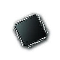
PIC18F87J72-I/PT Microchip Technology, PIC18F87J72-I/PT Datasheet - Page 424

PIC18F87J72-I/PT
Manufacturer Part Number
PIC18F87J72-I/PT
Description
IC PIC MCU 8BIT 14KB FLSH 80TQFP
Manufacturer
Microchip Technology
Series
PIC® 18Fr
Datasheet
1.PIC18F86J72-IPT.pdf
(480 pages)
Specifications of PIC18F87J72-I/PT
Program Memory Type
FLASH
Program Memory Size
128KB (64K x 16)
Package / Case
80-TQFP
Core Processor
PIC
Core Size
8-Bit
Speed
48MHz
Connectivity
I²C, LIN, SPI, UART/USART
Peripherals
Brown-out Detect/Reset, LCD, LVD, POR, PWM, WDT
Number Of I /o
51
Ram Size
3.8K x 8
Voltage - Supply (vcc/vdd)
2 V ~ 3.6 V
Data Converters
A/D 12x12b
Oscillator Type
Internal
Operating Temperature
-40°C ~ 85°C
Data Bus Width
8 bit
Data Ram Size
4 KB
Interface Type
SPI, USART, SPI, I2C
Maximum Clock Frequency
8 MHz
Number Of Programmable I/os
51
Number Of Timers
4
Operating Supply Voltage
2 V to 3.6 V
Maximum Operating Temperature
+ 85 C
Mounting Style
SMD/SMT
Minimum Operating Temperature
- 40 C
On-chip Adc
14
Controller Family/series
PIC18F
No. Of I/o's
51
Ram Memory Size
3923Byte
Cpu Speed
48MHz
No. Of Timers
4
Rohs Compliant
Yes
Lead Free Status / RoHS Status
Lead free / RoHS Compliant
Lead Free Status / RoHS Status
Lead free / RoHS Compliant, Lead free / RoHS Compliant
Available stocks
Company
Part Number
Manufacturer
Quantity
Price
Company:
Part Number:
PIC18F87J72-I/PT
Manufacturer:
Microchip
Quantity:
210
Company:
Part Number:
PIC18F87J72-I/PT
Manufacturer:
Microchip Technology
Quantity:
10 000
- Current page: 424 of 480
- Download datasheet (5Mb)
PIC18F87J72 FAMILY
TABLE 29-26: DUAL-CHANNEL AFE ELECTRICAL CHARACTERISTICS (CONTINUED)
DS39979A-page 424
Electrical Specifications: Unless otherwise indicated: SAV
MCLK = 4 MHz, PRESCALE = 1, OSR = 64, GAIN = 1, Dithering Off, V
ADC Performance (continued)
Integral Non-Linearity (Note 4)
Input Impedance
Signal-to-Noise and Distortion
Ratio (Notes 4, 6)
Total Harmonic Distortion
(Notes 4, 6)
Signal-to-Noise Ratio
(Notes 4, 6)
Spurious Free Dynamic Range
(Note 4)
Crosstalk (50/60 Hz) (Note 4)
AC Power Supply Rejection
DC Power Supply Rejection
DC Common-Mode Rejection
Ratio (Note 4)
Note 1:
2:
3:
4:
5:
6:
7:
8:
Parameters
Outside of this range, the ADC accuracy is not specified. An extended input range of ±6V can be applied
continuously to the part with no risk of damage.
For these operating currents, the following bit settings apply: SHUTDOWN<1:0> = 00, RESET<1:0> = 00,
VREFEXT = 0, CLKEXT = 0.
distortion or instability across this input range. Dynamic performance is specified at -0.5 dB below the maximum
signal range, V
See Appendix B.3 “Terminology and Formulas” for definitions.
Applies to all gains. Offset error is dependent on PGA gain setting.
This parameter is established by characterization and is not 100% tested.
For proper operation and to keep ADC accuracy, AMCLK should always be in the range of 1 to 5 MHz with
BOOST bits off. With BOOST bits on, AMCLK should be in the range of 1 to 8.192 MHz.
AMCLK = MCLK/PRESCALE.
For these operating currents, the following Configuration bit settings apply: SHUTDOWN<1:0> = 11,
VREFEXT = 1, CLKEXT = 1.
This specification implies that the ADC output is valid over this entire differential range and that there is no
IN
= -0.5 dBFS @ 50/60 Hz = 353 mV
DC PSRR
AC PSRR
Symbol
CTALK
SINAD
CMRR
SFDR
THD
SNR
INL
Z
IN
Preliminary
Min
350
—
—
—
—
—
—
—
—
—
—
—
—
—
DD
= 4.5 to 5.5V, SV
Typical
RMS
-101
-133
103
-82
-77
-77
-72
15
90
78
91
81
83
—
, mV
IN
REF
= -0.5, dBFS = 353 mV
Max
= 2.4V.
—
—
—
—
—
—
—
—
—
—
—
—
—
—
DD
= 2.7 to 5.5V, -40°C < T
Units
ppm
k
dB
dB
dB
dB
dB
dB
dB
dB
dB
dB
dB
dB
2010 Microchip Technology Inc.
GAIN = 1,
DITHER = ON
Proportional to
1/AMCLK
OSR = 256,
DITHER = ON
OSR = 64,
DITHER = OFF
OSR = 256,
DITHER = ON
OSR = 64,
DITHER = OFF
OSR = 256,
DITHER = ON
OSR = 64,
DITHER = OFF
OSR = 256,
DITHER = ON
OSR = 64,
DITHER = OFF
OSR = 256,
DITHER = ON
SAV
1 V
SAV
5.5V
V
+1V
RMS
CM
PP
DD
DD
varies from -1V to
@ 50/60 Hz
@ 50/60 Hz
Conditions
and SV
and SV
A
<+85°C,
DD
DD
= 4.5 to
= 5V +
Related parts for PIC18F87J72-I/PT
Image
Part Number
Description
Manufacturer
Datasheet
Request
R

Part Number:
Description:
Manufacturer:
Microchip Technology Inc.
Datasheet:

Part Number:
Description:
Manufacturer:
Microchip Technology Inc.
Datasheet:

Part Number:
Description:
Manufacturer:
Microchip Technology Inc.
Datasheet:

Part Number:
Description:
Manufacturer:
Microchip Technology Inc.
Datasheet:

Part Number:
Description:
Manufacturer:
Microchip Technology Inc.
Datasheet:

Part Number:
Description:
Manufacturer:
Microchip Technology Inc.
Datasheet:

Part Number:
Description:
Manufacturer:
Microchip Technology Inc.
Datasheet:

Part Number:
Description:
Manufacturer:
Microchip Technology Inc.
Datasheet:


