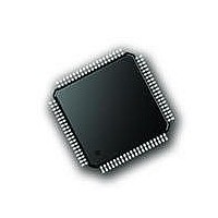
PIC18F87J72-I/PT Microchip Technology, PIC18F87J72-I/PT Datasheet - Page 291

PIC18F87J72-I/PT
Manufacturer Part Number
PIC18F87J72-I/PT
Description
IC PIC MCU 8BIT 14KB FLSH 80TQFP
Manufacturer
Microchip Technology
Series
PIC® 18Fr
Datasheet
1.PIC18F86J72-IPT.pdf
(480 pages)
Specifications of PIC18F87J72-I/PT
Program Memory Type
FLASH
Program Memory Size
128KB (64K x 16)
Package / Case
80-TQFP
Core Processor
PIC
Core Size
8-Bit
Speed
48MHz
Connectivity
I²C, LIN, SPI, UART/USART
Peripherals
Brown-out Detect/Reset, LCD, LVD, POR, PWM, WDT
Number Of I /o
51
Ram Size
3.8K x 8
Voltage - Supply (vcc/vdd)
2 V ~ 3.6 V
Data Converters
A/D 12x12b
Oscillator Type
Internal
Operating Temperature
-40°C ~ 85°C
Data Bus Width
8 bit
Data Ram Size
4 KB
Interface Type
SPI, USART, SPI, I2C
Maximum Clock Frequency
8 MHz
Number Of Programmable I/os
51
Number Of Timers
4
Operating Supply Voltage
2 V to 3.6 V
Maximum Operating Temperature
+ 85 C
Mounting Style
SMD/SMT
Minimum Operating Temperature
- 40 C
On-chip Adc
14
Controller Family/series
PIC18F
No. Of I/o's
51
Ram Memory Size
3923Byte
Cpu Speed
48MHz
No. Of Timers
4
Rohs Compliant
Yes
Lead Free Status / RoHS Status
Lead free / RoHS Compliant
Lead Free Status / RoHS Status
Lead free / RoHS Compliant, Lead free / RoHS Compliant
Available stocks
Company
Part Number
Manufacturer
Quantity
Price
Company:
Part Number:
PIC18F87J72-I/PT
Manufacturer:
Microchip
Quantity:
210
Company:
Part Number:
PIC18F87J72-I/PT
Manufacturer:
Microchip Technology
Quantity:
10 000
- Current page: 291 of 480
- Download datasheet (5Mb)
EXAMPLE 22-4:
2010 Microchip Technology Inc.
///////////////////////////////////////////////////////////////////////////////////////////////
// STEP 4: Write to AFE registers
// Initialize the AFE by writing to PHASE, GAIN, STATUS, CONFIG1 and CONFIG2 registers.
// Below is an example. The registers can be programmed with values as required
// by the application.
///////////////////////////////////////////////////////////////////////////////////////////////
///////////////////////////////////////////////////////////////////////////////////////////////
// Read from AFE registers to verify; this step is optional and does not affect AFE Operation.
// As an example, only GAIN, STATUS, CONFIG1 and CONFIG2 are read.
///////////////////////////////////////////////////////////////////////////////////////////////
LATDbits.LATD7=0;
if (SSPSTATbits.BF==1)
Dummy_Read=SSPBUF;
SSPBUF = 0x0E;
while(!SSPSTATbits.BF);
Dummy_Read=SSPBUF;
SSPBUF =0x00;
while(!SSPSTATbits.BF);
Dummy_Read=SSPBUF;
SSPBUF =0x04;
while(!SSPSTATbits.BF);
Dummy_Read=SSPBUF;
SSPBUF = 0xA0;
while(!SSPSTATbits.BF);
Dummy_Read=SSPBUF;
SSPBUF = 0x10;
while(!SSPSTATbits.BF);
Dummy_Read=SSPBUF;
SSPBUF = 0x01;
while(!SSPSTATbits.BF);
Dummy_Read=SSPBUF;
LATDbits.LATD7=1;
LATDbits.LATD7=0;
SSPBUF = 0x11;
while(!SSPSTATbits.BF);
Dummy_Read=SSPBUF;
SSPBUF =0x00;
while(!SSPSTATbits.BF);
D_S_ADC_data1=SSPBUF;
SSPBUF =0x00;
while(!SSPSTATbits.BF);
D_S_ADC_data2=SSPBUF;
SSPBUF =0x00;
while(!SSPSTATbits.BF);
D_S_ADC_data3=SSPBUF;
SSPBUF = 0x00;
while(!SSPSTATbits.BF);
D_S_ADC_data4=SSPBUF;
LATDbits.LATD7=1;
WRITING AND READING AFE REGISTERS THROUGH THE MSSP
//Chipselect enable for Delta Sigma ADC
//Address and Write command for Gain Register
// A6-A5--->00;A4-A0---->0x07;R/W---0 for write
//Dummy read to clear Buffer Full Status bit
//PHASE Register: No Delay
//Address automatically incremented GAIN Register
//CH1 gain 16, CH0 gain 1, No Boost
//Address automatically incremented STATUS Register
//Default values
//Address automatically incrementedData for CONFIG1 Register
//No Dither, Other values are default
//Address automatically incremented Data for CONFIG2 Register
//CLKEXT bit should be always programmed to 1
//Disable chip select after read/write of each set of registers
//Chip select enable for AFE
//Address and Read command for Gain Register
// A6-A5--->00;A4-A0---->0x08;R/W---1 for read
//Dummy read to clear Buffer Full Status bit
//Data from GAIN Register
//Data from STATUS Register, Address automatically incremented
//Data from CONFIG1 Register, Address automatically incremented
//Data from CONFIG2 Register, Address automatically incremented
//Disable chip select after read/write of each set of registers
Preliminary
PIC18F87J72 FAMILY
DS39979A-page 291
Related parts for PIC18F87J72-I/PT
Image
Part Number
Description
Manufacturer
Datasheet
Request
R

Part Number:
Description:
Manufacturer:
Microchip Technology Inc.
Datasheet:

Part Number:
Description:
Manufacturer:
Microchip Technology Inc.
Datasheet:

Part Number:
Description:
Manufacturer:
Microchip Technology Inc.
Datasheet:

Part Number:
Description:
Manufacturer:
Microchip Technology Inc.
Datasheet:

Part Number:
Description:
Manufacturer:
Microchip Technology Inc.
Datasheet:

Part Number:
Description:
Manufacturer:
Microchip Technology Inc.
Datasheet:

Part Number:
Description:
Manufacturer:
Microchip Technology Inc.
Datasheet:

Part Number:
Description:
Manufacturer:
Microchip Technology Inc.
Datasheet:


