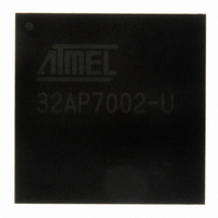
AT32AP7002-CTUT Atmel, AT32AP7002-CTUT Datasheet - Page 764

AT32AP7002-CTUT
Manufacturer Part Number
AT32AP7002-CTUT
Description
IC MCU 32BIT AVR32 196-CBGA
Manufacturer
Atmel
Series
AVR®32 AP7r
Specifications of AT32AP7002-CTUT
Core Processor
AVR
Core Size
32-Bit
Speed
150MHz
Connectivity
EBI/EMI, I²C, MMC, PS2, SPI, SSC, UART/USART, USB
Peripherals
AC'97, DMA, I²C, LCD, POR, PWM, WDT
Number Of I /o
85
Program Memory Type
ROMless
Ram Size
32K x 8
Voltage - Supply (vcc/vdd)
1.65 V ~ 1.95 V
Data Converters
D/A 2x16b
Oscillator Type
Internal
Operating Temperature
-40°C ~ 85°C
Package / Case
196-CBGA
Data Bus Width
32 bit
Data Ram Size
32 KB
Interface Type
I2C, JTAG, PS2, SPI, SSC, UART, USART, USB
Maximum Clock Frequency
150 MHz
Number Of Timers
3
Maximum Operating Temperature
+ 85 C
Mounting Style
SMD/SMT
Minimum Operating Temperature
- 40 C
On-chip Dac
16 bit, 2 Channel
Package
196CTBGA
Device Core
AVR32
Family Name
AT32
Maximum Speed
150 MHz
Operating Supply Voltage
1.8|3.3 V
For Use With
ATAVRONEKIT - KIT AVR/AVR32 DEBUGGER/PROGRMMRATNGW100 - KIT AVR32 NETWORK GATEWAYATSTK1000 - KIT STARTER FOR AVR32AP7000
Lead Free Status / RoHS Status
Lead free / RoHS Compliant
Eeprom Size
-
Program Memory Size
-
Lead Free Status / Rohs Status
Details
Available stocks
Company
Part Number
Manufacturer
Quantity
Price
- Current page: 764 of 896
- Download datasheet (13Mb)
AT32AP7002
For an STN display, all bits of the LCD Timing Configuration Register 1 must be written with 0:
LCDTIM1 = 0; // In STN mode, all bits must be zero
LCD Timing Configuration Register 2 contains 3 fields that control the horizontal back porch,
sync pulse, and front porch widths. This example will assume that a sync pulse width of 1 PCLK
cycle is desired and that front and back porch widths of 11 PCLK cycles are desired:
HBP = 11 - 1; // horizontal back porch of 11 PCLK cycles
HPW = 1 - 1; // horizontal pulse width of 1 PCLK cycle
HFP = 11 - 1; // horizontal front porch of 11 PCLK cycles
LCDTIM2 can then be written as follows:
LCDTIM2 = (HFP<<21) | (HPW<<8) | (HBP<<0);
The LCD Frame Configuration Register contains two fields, LINEVAL and HOZVAL. LINEVAL is
computed by subtracting 1 from the vertical display size (in pixels):
LINEVAL = 240 - 1;
For an STN display, HOZVAL is determined by dividing the horizontal display size (in bits) by the
number of data lines and then subtracting one. Because the STN display is color, the horizontal
display size in bits is 3 times the horizontal display size in pixels:
HOZVAL= ((3*320)/8) - 1;
If the value calculated for HOZVAL is not an integer, it must be rounded up to the next integer
value. LCDFRMCFG can then be written as follows:
LCDFRMCFG = (HOZVAL << 21) | (LINEVAL<<0);
The MODE Toggle Rate Value Register contains two fields, MVAL and MMODE, that determine
the MODE toggle rate. For this example it will be assumed that the desired mode toggle rate is 5
line periods:
MVAL = 5 - 1;
MMODE = 1; // Allow MVAL to determine the toggle rate
LCDMVAL can then be written as follows:
LCDMVAL = (MMODE<<31) | (MVAL<<0);
Finally, the BRSTLEN (Burst Length) and FRMSIZE (Frame Size) fields of the DMA Frame Con-
figuration Register must be determined. A desired burst length of 8 will be assumed:
BRSTLEN = 8 - 1;
The Frame Size is in units of 32-bit words, so it is determined by multiplying the number of pixels
in the display by the number of bits used for representing a pixel in memory and then dividing by
32:
FRMSIZE = ((320*240)*8) / 32;
DMAFRMCFG can then be written as follows:
DMAFRMCFG = (BRSTLEN<<24) | (FRMSIZE<<0);
764
32054F–AVR32–09/09
Related parts for AT32AP7002-CTUT
Image
Part Number
Description
Manufacturer
Datasheet
Request
R

Part Number:
Description:
DEV KIT FOR AVR/AVR32
Manufacturer:
Atmel
Datasheet:

Part Number:
Description:
INTERVAL AND WIPE/WASH WIPER CONTROL IC WITH DELAY
Manufacturer:
ATMEL Corporation
Datasheet:

Part Number:
Description:
Low-Voltage Voice-Switched IC for Hands-Free Operation
Manufacturer:
ATMEL Corporation
Datasheet:

Part Number:
Description:
MONOLITHIC INTEGRATED FEATUREPHONE CIRCUIT
Manufacturer:
ATMEL Corporation
Datasheet:

Part Number:
Description:
AM-FM Receiver IC U4255BM-M
Manufacturer:
ATMEL Corporation
Datasheet:

Part Number:
Description:
Monolithic Integrated Feature Phone Circuit
Manufacturer:
ATMEL Corporation
Datasheet:

Part Number:
Description:
Multistandard Video-IF and Quasi Parallel Sound Processing
Manufacturer:
ATMEL Corporation
Datasheet:

Part Number:
Description:
High-performance EE PLD
Manufacturer:
ATMEL Corporation
Datasheet:

Part Number:
Description:
8-bit Flash Microcontroller
Manufacturer:
ATMEL Corporation
Datasheet:

Part Number:
Description:
2-Wire Serial EEPROM
Manufacturer:
ATMEL Corporation
Datasheet:


