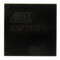
AT32AP7002-CTUT Atmel, AT32AP7002-CTUT Datasheet - Page 95

AT32AP7002-CTUT
Manufacturer Part Number
AT32AP7002-CTUT
Description
IC MCU 32BIT AVR32 196-CBGA
Manufacturer
Atmel
Series
AVR®32 AP7r
Specifications of AT32AP7002-CTUT
Core Processor
AVR
Core Size
32-Bit
Speed
150MHz
Connectivity
EBI/EMI, I²C, MMC, PS2, SPI, SSC, UART/USART, USB
Peripherals
AC'97, DMA, I²C, LCD, POR, PWM, WDT
Number Of I /o
85
Program Memory Type
ROMless
Ram Size
32K x 8
Voltage - Supply (vcc/vdd)
1.65 V ~ 1.95 V
Data Converters
D/A 2x16b
Oscillator Type
Internal
Operating Temperature
-40°C ~ 85°C
Package / Case
196-CBGA
Data Bus Width
32 bit
Data Ram Size
32 KB
Interface Type
I2C, JTAG, PS2, SPI, SSC, UART, USART, USB
Maximum Clock Frequency
150 MHz
Number Of Timers
3
Maximum Operating Temperature
+ 85 C
Mounting Style
SMD/SMT
Minimum Operating Temperature
- 40 C
On-chip Dac
16 bit, 2 Channel
Package
196CTBGA
Device Core
AVR32
Family Name
AT32
Maximum Speed
150 MHz
Operating Supply Voltage
1.8|3.3 V
For Use With
ATAVRONEKIT - KIT AVR/AVR32 DEBUGGER/PROGRMMRATNGW100 - KIT AVR32 NETWORK GATEWAYATSTK1000 - KIT STARTER FOR AVR32AP7000
Lead Free Status / RoHS Status
Lead free / RoHS Compliant
Eeprom Size
-
Program Memory Size
-
Lead Free Status / Rohs Status
Details
Available stocks
Company
Part Number
Manufacturer
Quantity
Price
- Current page: 95 of 896
- Download datasheet (13Mb)
10.4
10.4.1
10.4.2
10.5
10.5.1
10.5.2
32054F–AVR32–09/09
Product Dependencies
Functional Description
I/O Lines
Interrupt
Oscillator 0 and 1 operation
32 KHz oscillator operation
The PM provides a number of generic clock outputs, which can be connected to output pins,
multiplexed with PIO lines. The programmer must first program the PIO controller to assign
these pins to their peripheral function. If the I/O pins of the PM are not used by the application,
they can be used for other purposes by the PIO controller.
The PM also has a dedicated WAKE_N pin, as well as a number of pins for oscillators and
PLL’s, which do not require the PIO controller to be programmed.
The PM interrupt line is connected to one of the internal sources of the interrupt controller. Using
the PM interrupt requires the interrupt controller to be programmed first.
The two main oscillators are designed to be used with an external high frequency crystal, as
shown in
oscillators are enabled by default after reset, and are only switched off in sleep modes, as
described in
sleep mode that disabled the main oscillators, the oscillators need 128 slow clock cycles to sta-
bilize on the correct frequency.
period, to ensure that no unstable clocks propagate to the digital logic.
The oscillators can be bypassed by pulling the OSCEN_N pin high. This disables the oscillators,
and an external clock must be applied on XIN. No start-up time applies to this clock.
Figure 10-1. Oscillator connections
The 32 KHz oscillator operates similarly to Oscillator 0 and 1 described above, and is used to
generate the slow clock in the device. A 32768 Hz crystal must be connected between XIN32
and XOUT32 as shown in
remains enabled in all sleep modes except static mode, as described in
1. When waking up from Stop mode using external interrupts, the startup time is 32768 slow clock
cycles.
Figure
X O U T
Section 10.5.6 on page
X IN
10-1. See Electrical Characteristics for the allowed frequency range. The main
Figure
(1)
10-1. The 32 KHz oscillator is is an ultra-low power design, and
The PM masks the main oscillator outputs during this start-up
T y p . v a lu e s : C
101. After a power-on reset, or when waking up from a
2
= C
C
C
2
1
2
= 2 2 p F
AT32AP7002
Section 10.5.6 on page
95
Related parts for AT32AP7002-CTUT
Image
Part Number
Description
Manufacturer
Datasheet
Request
R

Part Number:
Description:
DEV KIT FOR AVR/AVR32
Manufacturer:
Atmel
Datasheet:

Part Number:
Description:
INTERVAL AND WIPE/WASH WIPER CONTROL IC WITH DELAY
Manufacturer:
ATMEL Corporation
Datasheet:

Part Number:
Description:
Low-Voltage Voice-Switched IC for Hands-Free Operation
Manufacturer:
ATMEL Corporation
Datasheet:

Part Number:
Description:
MONOLITHIC INTEGRATED FEATUREPHONE CIRCUIT
Manufacturer:
ATMEL Corporation
Datasheet:

Part Number:
Description:
AM-FM Receiver IC U4255BM-M
Manufacturer:
ATMEL Corporation
Datasheet:

Part Number:
Description:
Monolithic Integrated Feature Phone Circuit
Manufacturer:
ATMEL Corporation
Datasheet:

Part Number:
Description:
Multistandard Video-IF and Quasi Parallel Sound Processing
Manufacturer:
ATMEL Corporation
Datasheet:

Part Number:
Description:
High-performance EE PLD
Manufacturer:
ATMEL Corporation
Datasheet:

Part Number:
Description:
8-bit Flash Microcontroller
Manufacturer:
ATMEL Corporation
Datasheet:

Part Number:
Description:
2-Wire Serial EEPROM
Manufacturer:
ATMEL Corporation
Datasheet:


