IP-AGX-PCIE/4 Altera, IP-AGX-PCIE/4 Datasheet - Page 54
IP-AGX-PCIE/4
Manufacturer Part Number
IP-AGX-PCIE/4
Description
IP CORE - PCI Express X1 And X4 Lanes For Arria GX
Manufacturer
Altera
Datasheet
1.IP-AGX-PCIE1.pdf
(362 pages)
Specifications of IP-AGX-PCIE/4
Software Application
IP CORE, Interface And Protocols, PCI
Supported Families
Arria GX, Cyclone II, HardCopy II, Stratix II
Core Architecture
FPGA
Core Sub-architecture
Arria, Cyclone, Stratix
Rohs Compliant
NA
Lead Free Status / RoHS Status
na


3–12
Table 3–4. Buffer Setup Parameters (Part 3 of 3)
Power Management
Table 3–5. Power Management Parameters (Part 1 of 2)
PCI Express Compiler User Guide
RX Buffer Space
Allocation (per
VC)
Idle threshold for L0s
entry
Endpoint L0s
acceptable latency
Parameter
Parameter
1
Read-Only
table
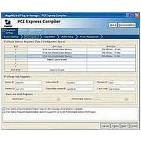
The Power Management page contains the parameters for setting various power
management properties of the IP core.
The Power Management page in the SOPC Builder flow does not include Simulation
Mode and Summary tabs.
Table 3–5
256 ns–8,192 ns
(in 256 ns
increments)
< 64 ns – > 4 µs
Value
Value
describes the parameters you can set on this page.
L0s Active State Power Management (ASPM)
Shows the credits and space allocated for each flow-controllable type, based on the
RX buffer size setting. All virtual channels use the same RX buffer space allocation.
The table does not show non-posted data credits because the IP core always
advertises infinite non-posted data credits and automatically has room for the
maximum number of dwords of data that can be associated with each non-posted
header.
The numbers shown for completion headers and completion data indicate how much
space is reserved in the RX buffer for completions. However, infinite completion
credits are advertised on the PCI Express link as is required for endpoints. It is up to
the application layer to manage the rate of non-posted requests to ensure that the
RX buffer completion space does not overflow. The hard IP RX buffer is fixed at 16
KBytes for Stratix IV GX devices and 4 KBytes for Arria II GX devices.
This design parameter indicates the idle threshold for L0s entry. This
parameter specifies the amount of time the link must be idle before the
transmitter transitions to L0s state. The PCI Express specification states
that this time should be no more than 7 μs, but the exact value is
implementation-specific. If you select the Arria GX, Arria II GX,
Cyclone IV GX, Stratix II GX, Stratix IV GX, or Stratix V GX PHY, this
parameter is disabled and set to its maximum value. If you are using an
external PHY, consult the PHY vendor's documentation to determine the
correct value for this parameter.
This design parameter indicates the acceptable endpoint L0s latency for the
device capabilities register. Sets the read-only value of the endpoint L0s
acceptable latency field of the device capabilities register (0x084). This
value should be based on how much latency the application layer can
tolerate. This setting is disabled for root ports.
Description
Description
December 2010 Altera Corporation
Chapter 3: Parameter Settings
Power Management
Related parts for IP-AGX-PCIE/4
Image
Part Number
Description
Manufacturer
Datasheet
Request
R

Part Number:
Description:
IP CORE - X1 Lane PCI Express For Arria GX
Manufacturer:
Altera
Datasheet:

Part Number:
Description:
CYCLONE II STARTER KIT EP2C20N
Manufacturer:
Altera
Datasheet:


Part Number:
Description:
CPLD, EP610 Family, ECMOS Process, 300 Gates, 16 Macro Cells, 16 Reg., 16 User I/Os, 5V Supply, 35 Speed Grade, 24DIP
Manufacturer:
Altera Corporation
Datasheet:
Part Number:
Description:
CPLD, EP610 Family, ECMOS Process, 300 Gates, 16 Macro Cells, 16 Reg., 16 User I/Os, 5V Supply, 15 Speed Grade, 24DIP
Manufacturer:
Altera Corporation
Datasheet:
Part Number:
Description:
Manufacturer:
Altera Corporation
Datasheet:
Part Number:
Description:
CPLD, EP610 Family, ECMOS Process, 300 Gates, 16 Macro Cells, 16 Reg., 16 User I/Os, 5V Supply, 30 Speed Grade, 24DIP
Manufacturer:
Altera Corporation
Datasheet:
Part Number:
Description:
High-performance, low-power erasable programmable logic devices with 8 macrocells, 10ns
Manufacturer:
Altera Corporation
Datasheet:
Part Number:
Description:
High-performance, low-power erasable programmable logic devices with 8 macrocells, 7ns
Manufacturer:
Altera Corporation
Datasheet:
Part Number:
Description:
Classic EPLD
Manufacturer:
Altera Corporation
Datasheet:
Part Number:
Description:
High-performance, low-power erasable programmable logic devices with 8 macrocells, 10ns
Manufacturer:
Altera Corporation
Datasheet:
Part Number:
Description:
Manufacturer:
Altera Corporation
Datasheet:
Part Number:
Description:
Manufacturer:
Altera Corporation
Datasheet:
Part Number:
Description:
Manufacturer:
Altera Corporation
Datasheet: