MPC8379EVRAJF Freescale Semiconductor, MPC8379EVRAJF Datasheet - Page 105
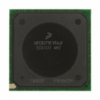
MPC8379EVRAJF
Manufacturer Part Number
MPC8379EVRAJF
Description
MPU PWRQUICC II 533MHZ 689TEPBGA
Manufacturer
Freescale Semiconductor
Series
PowerQUICC II PROr
Datasheets
1.MPC8377EVRAGD.pdf
(126 pages)
2.MPC8377EVRAGD.pdf
(2 pages)
3.MPC8379VRAGD.pdf
(116 pages)
Specifications of MPC8379EVRAJF
Processor Type
MPC83xx PowerQUICC II Pro 32-Bit
Speed
533MHz
Voltage
1V
Mounting Type
Surface Mount
Package / Case
689-TePBGA II
Maximum Clock Frequency
533 MHz
Operating Supply Voltage
1.8 V to 2.5 V
Maximum Operating Temperature
+ 105 C
Mounting Style
SMD/SMT
I/o Voltage
1.8 V, 2.5 V, 3.3 V
Minimum Operating Temperature
0 C
Core Size
32 Bit
Program Memory Size
64KB
Cpu Speed
533MHz
Embedded Interface Type
DUART, HSSI, I2C, IPIC, JTAG, SPI, USB
Digital Ic Case Style
BGA
No. Of Pins
689
Rohs Compliant
Yes
For Use With
MPC8377E-RDBA - BOARD REF DES MPC8377 REV 2.1MPC8377E-MDS-PB - BOARD MODULAR DEV SYSTEM
Lead Free Status / RoHS Status
Lead free / RoHS Compliant
Features
-
Lead Free Status / Rohs Status
Lead free / RoHS Compliant
Available stocks
Company
Part Number
Manufacturer
Quantity
Price
Company:

Part Number:
MPC8379EVRAJF
Manufacturer:
Freescale Semiconductor
Quantity:
135
Company:
Part Number:
MPC8379EVRAJF
Manufacturer:
Freescale Semiconductor
Quantity:
10 000


Freescale Semiconductor
Note:
1
2
3
4
5
6
7
8
9
10
11
12
13
14
15
16
This pin is an open drain signal. A weak pull-up resistor (1 kΩ) should be placed on this pin to OVDD.
This pin is an open drain signal. A weak pull-up resistor (2–10 kΩ) should be placed on this pin to OVDD.
This output is actively driven during reset rather than being released to high impedance during reset.
These JTAG pins have weak internal pull-up P-FETs that are always enabled.
This pin should have a weak pull up if the chip is in PCI host mode. Follow PCI Specification recommendation and see
AN3665, “MPC837xE Design Checklist,” for more details.
These are On Die Termination pins, used to control DDR2 memories internal termination resistance.
This pin must always be tied to GND using a 0 Ω resistor.
This pin must always be left not connected.
For DDR2 operation, it is recommended that MDIC0 be tied to GND using an 18.2 Ω resistor and MDIC1 be tied to DDR
power using an 18.2 Ω resistor.
This pin must always be tied low. If it is left floating it may cause the device to malfunction.
See AN3665, “MPC837xE Design Checklist,” for proper DDR termination.
This pin must not be pulled down during PORESET.
This pin must always be tied to OVDD.
Open or tie to GND.
Voltage settings are dependent on the frequency used; see
See AN3665, “MPC837xE Design Checklist,” for proper eTSEC termination.
Pull Down
AVDD_C
AVDD_P
AVDD_L
Signal
GVDD
OVDD
NC
MPC8377E PowerQUICC II Pro Processor Hardware Specifications, Rev. 4
V5, AA5, AD5, N6, R6, AJ6, B7, E7, K7, AA7,
L25, W25, AB26, U27, M28, Y28, G10, A11,
N3, Y3, AB3, B4, P4, AF4, AH4, C5, F5, K5,
A2, D2, R2, U2, AC2, AF2, AJ2, F3, H3, L3,
AC10, AF12, AJ12, K23, Y23, R24, AD24,
Table 72. TePBGA II Pinout Listing (continued)
F16, F17, AD16, AD17
Package Pin Number
AE7, AG7, AD8
B16, AH18
AD13
C11
F13
F12
No Connect
Pull Down
Table
3.
(1.0 V or 1.05 V)
core PLL (1.0 V
Power for eLBC
Power for e300
Power for DDR
other Standard
Voltage (2.5 or
PCI, USB, and
PLL (1.0 V or
system PLL
SDRAM I/O
or 1.05 V)
Pin Type
Power for
1.05 V)
(3.3 V)
1.8 V)
—
—
Power Supply
Package and Pin Listings
GVDD
OVDD
—
—
—
—
—
Notes
15
15
15
—
—
8
7
105
Related parts for MPC8379EVRAJF
Image
Part Number
Description
Manufacturer
Datasheet
Request
R

Part Number:
Description:
BOARD REF DESIGN MPC8379E
Manufacturer:
Freescale Semiconductor
Datasheet:

Part Number:
Description:
BOARD REFERENCE FOR MPC837
Manufacturer:
Freescale Semiconductor
Datasheet:
Part Number:
Description:
BOARD PROCESSOR FOR MDS S
Manufacturer:
Freescale Semiconductor
Datasheet:

Part Number:
Description:
Powerquicc Ii Pro Processor Hardware Specifications
Manufacturer:
Freescale Semiconductor, Inc
Datasheet:

Part Number:
Description:
BOARD REF DES MPC8377 REV 2.1
Manufacturer:
Freescale Semiconductor
Datasheet:
Part Number:
Description:
Manufacturer:
Freescale Semiconductor, Inc
Datasheet:
Part Number:
Description:
Manufacturer:
Freescale Semiconductor, Inc
Datasheet:
Part Number:
Description:
Manufacturer:
Freescale Semiconductor, Inc
Datasheet:
Part Number:
Description:
Manufacturer:
Freescale Semiconductor, Inc
Datasheet:
Part Number:
Description:
Manufacturer:
Freescale Semiconductor, Inc
Datasheet:
Part Number:
Description:
Manufacturer:
Freescale Semiconductor, Inc
Datasheet:
Part Number:
Description:
Manufacturer:
Freescale Semiconductor, Inc
Datasheet:
Part Number:
Description:
Manufacturer:
Freescale Semiconductor, Inc
Datasheet:
Part Number:
Description:
Manufacturer:
Freescale Semiconductor, Inc
Datasheet:
Part Number:
Description:
Manufacturer:
Freescale Semiconductor, Inc
Datasheet: