DEMO9S08LC60 Freescale Semiconductor, DEMO9S08LC60 Datasheet - Page 137
DEMO9S08LC60
Manufacturer Part Number
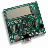
DEMO9S08LC60
Description
BOARD DEMO FOR 9S08LC60
Manufacturer
Freescale Semiconductor
Type
MCUr
Datasheets
1.DEMO9S08LC60.pdf
(360 pages)
2.DEMO9S08LC60.pdf
(32 pages)
3.DEMO9S08LC60.pdf
(2 pages)
Specifications of DEMO9S08LC60
Contents
Evaluation Board
Processor To Be Evaluated
MC9S08LC60
Interface Type
RS-232, USB
Silicon Manufacturer
Freescale
Core Architecture
HCS08
Core Sub-architecture
HCS08
Silicon Core Number
MC9S08
Silicon Family Name
S08LC
Rohs Compliant
Yes
For Use With/related Products
MC9S08LC60
Lead Free Status / RoHS Status
Lead free / RoHS Compliant


9.4
This section provides a complete functional description of the LCD block, detailing the operation of the
design from the end-user perspective.
Before enabling the LCD module by asserting the LCDEN bit in the LCDCR0 register, it is recommended
that the LCD module be configured based on the end application requirements. Out of reset, the LCD
module is configured with default settings, but these settings are not optimal for every application. The
LCD module provides several versatile configuration settings and options to support varied
implementation requirements including:
The LCD module also provides a frontplane enable control. Setting the frontplane enable bit, FP[n]EN, for
a particular pin enables the LCD module functionality of that pin when the LCDEN bit is set. When both
the LCDEN and required FP[n]EN bits are set, the LCDRAM can then be used to activate (display) the
corresponding LCD segments on an LCD panel.
The LCDRAM registers control the on/off state for the FP and BP segments of the LCD when the
LCDDRMS bit in the LCDCMD is cleared.If LCDDRMS = 0 when a 1 is written to the FP[n]BP[x] bit,
the corresponding connected segment turns on.When a 0 is written, the segment is turned off. For a detailed
description of LCD module operation for a basic seven-segment LCD display, see
Seven Segment Example
Freescale Semiconductor
LCDCLR
BLANK
•
•
•
•
Field
1
0
Frame frequency
Duty cycle
Frame frequency interrupt enable
Blinking frequency and options
Functional Description
LCD Data Register Clear Command — Deasserts all accessible bits in the LCDRAM registers. To clear all LCD
segment blink enables in the LCDRAM registers, the LCDCLR bit must be asserted only while LCDDRMS = 1.To
clear the entire LCD display, the LCDCLR bit must be asserted only while LCDDRMS = 0.
0 Contents of LCD data register are not deasserted by hardware.
1 Deasserts all accessible bits in the LCDRAM registers. The LCDDLR bit clears after all accessible bits in the
LCD Display Blank Command — Asserting this bit clears all segments in the LCD display regardless of the
contents of the LCDRAM registers or the state of the LCDDRMS bit. BLANK does not disable the LCD timing
generator.
0 LCD segments are displayed or cleared depending on the contents of the LCDRAM registers when the
1 LCD segments are cleared regardless of the contents of the LCDRAM registers or the state of the LCDDRMS
LCDRAM registers are set to 0.
LCDDRMS bit is clear.
bit. The content of the LCDRAM registers is unchanged by the BLANK bit.
Description”.
MC9S08LC60 Series Data Sheet: Technical Data, Rev. 4
Table 9-12. LCDCMD Field Descriptions
Description
Chapter 9 Liquid Crystal Display Driver (S08LCDV1)
Section 9.6.1, “LCD
137
Related parts for DEMO9S08LC60
Image
Part Number
Description
Manufacturer
Datasheet
Request
R

Part Number:
Description:
Manufacturer:
Freescale Semiconductor, Inc
Datasheet:
Part Number:
Description:
Manufacturer:
Freescale Semiconductor, Inc
Datasheet:
Part Number:
Description:
Manufacturer:
Freescale Semiconductor, Inc
Datasheet:
Part Number:
Description:
Manufacturer:
Freescale Semiconductor, Inc
Datasheet:
Part Number:
Description:
Manufacturer:
Freescale Semiconductor, Inc
Datasheet:
Part Number:
Description:
Manufacturer:
Freescale Semiconductor, Inc
Datasheet:
Part Number:
Description:
Manufacturer:
Freescale Semiconductor, Inc
Datasheet:
Part Number:
Description:
Manufacturer:
Freescale Semiconductor, Inc
Datasheet:
Part Number:
Description:
Manufacturer:
Freescale Semiconductor, Inc
Datasheet:
Part Number:
Description:
Manufacturer:
Freescale Semiconductor, Inc
Datasheet:
Part Number:
Description:
Manufacturer:
Freescale Semiconductor, Inc
Datasheet:
Part Number:
Description:
Manufacturer:
Freescale Semiconductor, Inc
Datasheet:
Part Number:
Description:
Manufacturer:
Freescale Semiconductor, Inc
Datasheet:
Part Number:
Description:
Manufacturer:
Freescale Semiconductor, Inc
Datasheet:
Part Number:
Description:
Manufacturer:
Freescale Semiconductor, Inc
Datasheet: