DEMO9S08LC60 Freescale Semiconductor, DEMO9S08LC60 Datasheet - Page 325
DEMO9S08LC60
Manufacturer Part Number
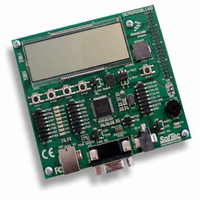
DEMO9S08LC60
Description
BOARD DEMO FOR 9S08LC60
Manufacturer
Freescale Semiconductor
Type
MCUr
Datasheets
1.DEMO9S08LC60.pdf
(360 pages)
2.DEMO9S08LC60.pdf
(32 pages)
3.DEMO9S08LC60.pdf
(2 pages)
Specifications of DEMO9S08LC60
Contents
Evaluation Board
Processor To Be Evaluated
MC9S08LC60
Interface Type
RS-232, USB
Silicon Manufacturer
Freescale
Core Architecture
HCS08
Core Sub-architecture
HCS08
Silicon Core Number
MC9S08
Silicon Family Name
S08LC
Rohs Compliant
Yes
For Use With/related Products
MC9S08LC60
Lead Free Status / RoHS Status
Lead free / RoHS Compliant


where K is a constant pertaining to the particular part. K can be determined from
measuring P
obtained by solving equations 1 and 2 iteratively for any value of T
A.4
Although damage from static discharge is much less common on these devices than on early CMOS
circuits, normal handling precautions should be used to avoid exposure to static discharge. Qualification
tests are performed to ensure that these devices can withstand exposure to reasonable levels of static
without suffering any permanent damage. All ESD testing is in conformity with CDF-AEC-Q00 Stress
Test Qualification for Automotive Grade Integrated Circuits. (http://www.aecouncil.com/) This device was
qualified to AEC-Q100 Rev E. A device is considered to have failed if, after exposure to ESD pulses, the
device no longer meets the device specification requirements. Complete dc parametric and functional
testing is performed per the applicable device specification at room temperature followed by hot
temperature, unless specified otherwise in the device specification.
Freescale Semiconductor
Electrostatic Discharge (ESD) Protection Characteristics
1
D
Latch-up
Machine
Parameter is achieved by design characterization on a small sample size from typical devices
under typical conditions unless otherwise noted.
Model
Human
(at equilibrium) for a known T
Body
No.
1
2
3
4
Series resistance
Storage capacitance
Number of pulses per pin
Series resistance
Storage capacitance
Number of pulses per pin
Minimum input voltage limit
Maximum input voltage limit
Human body model (HBM)
Machine model (MM)
Charge device model (CDM)
Latch-up current at T
Table A-4. ESD and Latch-Up Protection Characteristics
MC9S08LC60 Series Data Sheet: Technical Data, Rev. 4
Table A-3. ESD and Latch-up Test Conditions
K = P
Description
Rating
D
× (T
(1)
A
= 85°C
A
+ 273°C) + θ
A
. Using this value of K, the values of P
Symbol
Symbol
V
V
JA
V
I
R1
R1
HBM
CDM
LAT
—
—
C
C
MM
× (P
D
)
2
± 2000
A
± 200
± 500
± 100
Min
.
Value
1500
100
200
1.8
3.6
3
0
3
Appendix A Electrical Characteristics
Max
—
—
—
—
Equation A-3
D
and T
Unit
Unit
mA
pF
pF
Ω
Ω
V
V
V
V
V
J
can be
by
Eqn. A-3
325
Related parts for DEMO9S08LC60
Image
Part Number
Description
Manufacturer
Datasheet
Request
R

Part Number:
Description:
Manufacturer:
Freescale Semiconductor, Inc
Datasheet:
Part Number:
Description:
Manufacturer:
Freescale Semiconductor, Inc
Datasheet:
Part Number:
Description:
Manufacturer:
Freescale Semiconductor, Inc
Datasheet:
Part Number:
Description:
Manufacturer:
Freescale Semiconductor, Inc
Datasheet:
Part Number:
Description:
Manufacturer:
Freescale Semiconductor, Inc
Datasheet:
Part Number:
Description:
Manufacturer:
Freescale Semiconductor, Inc
Datasheet:
Part Number:
Description:
Manufacturer:
Freescale Semiconductor, Inc
Datasheet:
Part Number:
Description:
Manufacturer:
Freescale Semiconductor, Inc
Datasheet:
Part Number:
Description:
Manufacturer:
Freescale Semiconductor, Inc
Datasheet:
Part Number:
Description:
Manufacturer:
Freescale Semiconductor, Inc
Datasheet:
Part Number:
Description:
Manufacturer:
Freescale Semiconductor, Inc
Datasheet:
Part Number:
Description:
Manufacturer:
Freescale Semiconductor, Inc
Datasheet:
Part Number:
Description:
Manufacturer:
Freescale Semiconductor, Inc
Datasheet:
Part Number:
Description:
Manufacturer:
Freescale Semiconductor, Inc
Datasheet:
Part Number:
Description:
Manufacturer:
Freescale Semiconductor, Inc
Datasheet: