DEMO9S08LC60 Freescale Semiconductor, DEMO9S08LC60 Datasheet - Page 210
DEMO9S08LC60
Manufacturer Part Number
DEMO9S08LC60
Description
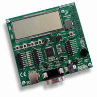
BOARD DEMO FOR 9S08LC60
Manufacturer
Freescale Semiconductor
Type
MCUr
Datasheets
1.DEMO9S08LC60.pdf
(360 pages)
2.DEMO9S08LC60.pdf
(32 pages)
3.DEMO9S08LC60.pdf
(2 pages)
Specifications of DEMO9S08LC60
Contents
Evaluation Board
Processor To Be Evaluated
MC9S08LC60
Interface Type
RS-232, USB
Silicon Manufacturer
Freescale
Core Architecture
HCS08
Core Sub-architecture
HCS08
Silicon Core Number
MC9S08
Silicon Family Name
S08LC
Rohs Compliant
Yes
For Use With/related Products
MC9S08LC60
Lead Free Status / RoHS Status
Lead free / RoHS Compliant


Chapter 11 Timer/Pulse-Width Modulator (S08TPMV2)
11.4.3
This type of PWM output uses the up-/down-counting mode of the timer counter (CPWMS = 1). The
output compare value in TPMxCnVH:TPMxCnVL determines the pulse width (duty cycle) of the PWM
signal and the period is determined by the value in TPMxMODH:TPMxMODL.
TPMxMODH:TPMxMODL should be kept in the range of 0x0001 to 0x7FFF because values outside this
range can produce ambiguous results. ELSnA will determine the polarity of the CPWM output.
If the channel value register TPMxCnVH:TPMxCnVL is zero or negative (bit 15 set), the duty cycle will
be 0%. If TPMxCnVH:TPMxCnVL is a positive value (bit 15 clear) and is greater than the (nonzero)
modulus setting, the duty cycle will be 100% because the duty cycle compare will never occur. This
implies the usable range of periods set by the modulus register is 0x0001 through 0x7FFE (0x7FFF if
generation of 100% duty cycle is not necessary). This is not a significant limitation because the resulting
period is much longer than required for normal applications.
TPMxMODH:TPMxMODL = 0x0000 is a special case that should not be used with center-aligned PWM
mode. When CPWMS = 0, this case corresponds to the counter running free from 0x0000 through
0xFFFF, but when CPWMS = 1 the counter needs a valid match to the modulus register somewhere other
than at 0x0000 in order to change directions from up-counting to down-counting.
Figure 11-12
determines the pulse width (duty cycle) of the CPWM signal. If ELSnA = 0, the compare match while
counting up forces the CPWM output signal low and a compare match while counting down forces the
output high. The counter counts up until it reaches the modulo setting in TPMxMODH:TPMxMODL, then
counts down until it reaches zero. This sets the period equal to two times TPMxMODH:TPMxMODL.
Center-aligned PWM outputs typically produce less noise than edge-aligned PWMs because fewer I/O pin
transitions are lined up at the same system clock edge. This type of PWM is also required for some types
of motor drives.
Because the HCS08 is a family of 8-bit MCUs, the settings in the timer channel registers are buffered to
ensure coherent 16-bit updates and to avoid unexpected PWM pulse widths. Writes to any of the registers,
TPMxMODH, TPMxMODL, TPMxCnVH, and TPMxCnVL, actually write to buffer registers. Values are
210
Center-Aligned PWM Mode
shows the output compare value in the TPM channel registers (multiplied by 2), which
TPMxMODH:TPMx
TPM1C
COUNT =
Figure 11-12. CPWM Period and Pulse Width (ELSnA = 0)
pulse width = 2 x (TPMxCnVH:TPMxCnVL)
MC9S08LC60 Series Data Sheet: Technical Data, Rev. 4
period = 2 x (TPMxMODH:TPMxMODL);
for TPMxMODH:TPMxMODL = 0x0001–0x7FFF
(COUNT DOWN)
COMPARE
OUTPUT
2 x
2 x
PULSE WIDTH
COUNT = 0
PERIOD
(COUNT UP)
COMPARE
OUTPUT
TPMxMODH:TPMx
COUNT =
Freescale Semiconductor
Eqn. 11-1
Eqn. 11-2
Related parts for DEMO9S08LC60
Image
Part Number
Description
Manufacturer
Datasheet
Request
R

Part Number:
Description:
Manufacturer:
Freescale Semiconductor, Inc
Datasheet:
Part Number:
Description:
Manufacturer:
Freescale Semiconductor, Inc
Datasheet:
Part Number:
Description:
Manufacturer:
Freescale Semiconductor, Inc
Datasheet:
Part Number:
Description:
Manufacturer:
Freescale Semiconductor, Inc
Datasheet:
Part Number:
Description:
Manufacturer:
Freescale Semiconductor, Inc
Datasheet:
Part Number:
Description:
Manufacturer:
Freescale Semiconductor, Inc
Datasheet:
Part Number:
Description:
Manufacturer:
Freescale Semiconductor, Inc
Datasheet:
Part Number:
Description:
Manufacturer:
Freescale Semiconductor, Inc
Datasheet:
Part Number:
Description:
Manufacturer:
Freescale Semiconductor, Inc
Datasheet:
Part Number:
Description:
Manufacturer:
Freescale Semiconductor, Inc
Datasheet:
Part Number:
Description:
Manufacturer:
Freescale Semiconductor, Inc
Datasheet:
Part Number:
Description:
Manufacturer:
Freescale Semiconductor, Inc
Datasheet:
Part Number:
Description:
Manufacturer:
Freescale Semiconductor, Inc
Datasheet:
Part Number:
Description:
Manufacturer:
Freescale Semiconductor, Inc
Datasheet:
Part Number:
Description:
Manufacturer:
Freescale Semiconductor, Inc
Datasheet: