DEMO9S08LC60 Freescale Semiconductor, DEMO9S08LC60 Datasheet - Page 187
DEMO9S08LC60
Manufacturer Part Number
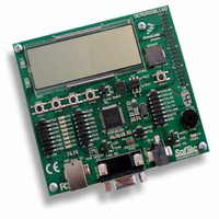
DEMO9S08LC60
Description
BOARD DEMO FOR 9S08LC60
Manufacturer
Freescale Semiconductor
Type
MCUr
Datasheets
1.DEMO9S08LC60.pdf
(360 pages)
2.DEMO9S08LC60.pdf
(32 pages)
3.DEMO9S08LC60.pdf
(2 pages)
Specifications of DEMO9S08LC60
Contents
Evaluation Board
Processor To Be Evaluated
MC9S08LC60
Interface Type
RS-232, USB
Silicon Manufacturer
Freescale
Core Architecture
HCS08
Core Sub-architecture
HCS08
Silicon Core Number
MC9S08
Silicon Family Name
S08LC
Rohs Compliant
Yes
For Use With/related Products
MC9S08LC60
Lead Free Status / RoHS Status
Lead free / RoHS Compliant


10.5.11 Fixed Frequency Clock
The ICG provides a fixed frequency clock output, XCLK, for use by on-chip peripherals. This output is
equal to the internal bus clock, BUSCLK, in all modes except FEE. In FEE mode, XCLK is equal to
ICGERCLK ÷ 2 when the following conditions are met:
If the above conditions are not true, then XCLK is equal to BUSCLK.
When the ICG is in either FEI or SCM mode, XCLK is turned off. Any peripherals which can use XCLK
as a clock source must not do so when the ICG is in FEI or SCM mode.
10.5.12 High Gain Oscillator
The oscillator has the option of running in a high gain oscillator (HGO) mode, which improves the
oscillator's resistance to EMC noise when running in FBE or FEE modes. This option is selected by writing
a 1 to the HGO bit in the ICGC1 register. HGO is used with both the high and low range oscillators but is
only valid when REFS = 1 in the ICGC1 register. When HGO = 0, the standard low-power oscillator is
selected. This bit is writable only once after any reset.
10.6
10.6.1
The section is intended to give some basic direction on which configuration a user would want to select
when initializing the ICG. For some applications, the serial communication link may dictate the accuracy
of the clock reference. For other applications, lowest power consumption may be the chief clock
consideration. Still others may have lowest cost as the primary goal. The ICG allows great flexibility in
choosing which is best for any application.
Freescale Semiconductor
•
•
(P × N) ÷ R ≥ 4 where P is determined by RANGE (see
MFD and RFD respectively (see
LOCK = 1.
Initialization/Application Information
Introduction
MC9S08LC60 Series Data Sheet: Technical Data, Rev. 4
Table
10-12).
Table
Chapter 10 Internal Clock Generator (S08ICGV4)
10-11), N and R are determined by
187
Related parts for DEMO9S08LC60
Image
Part Number
Description
Manufacturer
Datasheet
Request
R

Part Number:
Description:
Manufacturer:
Freescale Semiconductor, Inc
Datasheet:
Part Number:
Description:
Manufacturer:
Freescale Semiconductor, Inc
Datasheet:
Part Number:
Description:
Manufacturer:
Freescale Semiconductor, Inc
Datasheet:
Part Number:
Description:
Manufacturer:
Freescale Semiconductor, Inc
Datasheet:
Part Number:
Description:
Manufacturer:
Freescale Semiconductor, Inc
Datasheet:
Part Number:
Description:
Manufacturer:
Freescale Semiconductor, Inc
Datasheet:
Part Number:
Description:
Manufacturer:
Freescale Semiconductor, Inc
Datasheet:
Part Number:
Description:
Manufacturer:
Freescale Semiconductor, Inc
Datasheet:
Part Number:
Description:
Manufacturer:
Freescale Semiconductor, Inc
Datasheet:
Part Number:
Description:
Manufacturer:
Freescale Semiconductor, Inc
Datasheet:
Part Number:
Description:
Manufacturer:
Freescale Semiconductor, Inc
Datasheet:
Part Number:
Description:
Manufacturer:
Freescale Semiconductor, Inc
Datasheet:
Part Number:
Description:
Manufacturer:
Freescale Semiconductor, Inc
Datasheet:
Part Number:
Description:
Manufacturer:
Freescale Semiconductor, Inc
Datasheet:
Part Number:
Description:
Manufacturer:
Freescale Semiconductor, Inc
Datasheet: