DEMO9S08LC60 Freescale Semiconductor, DEMO9S08LC60 Datasheet - Page 188
DEMO9S08LC60
Manufacturer Part Number
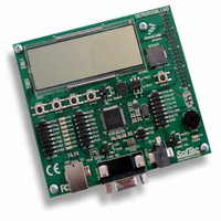
DEMO9S08LC60
Description
BOARD DEMO FOR 9S08LC60
Manufacturer
Freescale Semiconductor
Type
MCUr
Datasheets
1.DEMO9S08LC60.pdf
(360 pages)
2.DEMO9S08LC60.pdf
(32 pages)
3.DEMO9S08LC60.pdf
(2 pages)
Specifications of DEMO9S08LC60
Contents
Evaluation Board
Processor To Be Evaluated
MC9S08LC60
Interface Type
RS-232, USB
Silicon Manufacturer
Freescale
Core Architecture
HCS08
Core Sub-architecture
HCS08
Silicon Core Number
MC9S08
Silicon Family Name
S08LC
Rohs Compliant
Yes
For Use With/related Products
MC9S08LC60
Lead Free Status / RoHS Status
Lead free / RoHS Compliant


Chapter 10 Internal Clock Generator (S08ICGV4)
The following sections contain initialization examples for various configurations.
Important configuration information is repeated here for reference.
1
188
1
SCM — self-clocked mode (FLL bypassed
internal)
FBE — FLL bypassed external
FEI — FLL engaged internal
FEE — FLL engaged external
Ensure that
MFD Value
The IRG typically consumes 100 μA. The FLL and DCO typically consumes 0.5 to 2.5 mA, depending upon output frequency.
For minimum power consumption and minimum jitter, choose N and R to be as small as possible.
Bypassed
Engaged
FLL
FLL
000
001
010
011
100
f
ICGDCLK
Clock Scheme
Hexadecimal values designated by a preceding $, binary values designated
by a preceding %, and decimal values have no preceding character.
FEI
4 MHz < f
Medium power (will be less than FEE if oscillator
range = high)
Good clock accuracy (After IRG is trimmed)
Lowest system cost (no external components
required)
IRG is on. DCO is on.
SCM
This mode is mainly provided for quick and reliable
system startup.
3 MHz < f
3 MHz < f
Medium power
Poor accuracy.
IRG is off. DCO is on and open loop.
Multiplication Factor (N)
, which is equal to
Clock Reference Source = Internal
Bus
Bus
Bus
< 20 MHz.
< 5 MHz (default).
< 20 MHz (via filter bits).
Table 10-11. ICGOUT Frequency Calculation Options
MC9S08LC60 Series Data Sheet: Technical Data, Rev. 4
10
12
Table 10-10. ICG Configuration Consideration
4
6
8
Table 10-12. MFD and RFD Decode Table
1
f
ICGOUT
(f
IRG
* R, does not exceed f
f
ext
f
ICGDCLK
/ 7)* 64 * N / R
f
ICGOUT
f
* P * N / R
ext
NOTE
/ R
/ R
1
FEE
4 MHz < f
Medium power (will be less than FEI if oscillator
range = low)
High clock accuracy
Medium/High system cost (crystal, resonator or
external clock source required)
IRG is off. DCO is on.
FBE
f
used.
Lowest power
Highest clock accuracy
Medium/High system cost (Crystal, resonator or
external clock source required)
IRG is off. DCO is off.
RFD
Bus
000
001
010
011
100
Range = 0 ; P = 64
Range = 1; P = 1
ICGDCLKmax
range ≤ 8 MHz when crystal or resonator is
Clock Reference Source = External
Bus
NA
NA
64
P
< 20 MHz
.
Division Factor (R)
Typical f
immediately after reset
Typical f
Freescale Semiconductor
÷16
÷1
÷2
÷4
÷8
ICGOUT
IRG
Note
= 243 kHz
= 8 MHz
Related parts for DEMO9S08LC60
Image
Part Number
Description
Manufacturer
Datasheet
Request
R

Part Number:
Description:
Manufacturer:
Freescale Semiconductor, Inc
Datasheet:
Part Number:
Description:
Manufacturer:
Freescale Semiconductor, Inc
Datasheet:
Part Number:
Description:
Manufacturer:
Freescale Semiconductor, Inc
Datasheet:
Part Number:
Description:
Manufacturer:
Freescale Semiconductor, Inc
Datasheet:
Part Number:
Description:
Manufacturer:
Freescale Semiconductor, Inc
Datasheet:
Part Number:
Description:
Manufacturer:
Freescale Semiconductor, Inc
Datasheet:
Part Number:
Description:
Manufacturer:
Freescale Semiconductor, Inc
Datasheet:
Part Number:
Description:
Manufacturer:
Freescale Semiconductor, Inc
Datasheet:
Part Number:
Description:
Manufacturer:
Freescale Semiconductor, Inc
Datasheet:
Part Number:
Description:
Manufacturer:
Freescale Semiconductor, Inc
Datasheet:
Part Number:
Description:
Manufacturer:
Freescale Semiconductor, Inc
Datasheet:
Part Number:
Description:
Manufacturer:
Freescale Semiconductor, Inc
Datasheet:
Part Number:
Description:
Manufacturer:
Freescale Semiconductor, Inc
Datasheet:
Part Number:
Description:
Manufacturer:
Freescale Semiconductor, Inc
Datasheet:
Part Number:
Description:
Manufacturer:
Freescale Semiconductor, Inc
Datasheet: