DEMO9S08LC60 Freescale Semiconductor, DEMO9S08LC60 Datasheet - Page 259
DEMO9S08LC60
Manufacturer Part Number
DEMO9S08LC60
Description
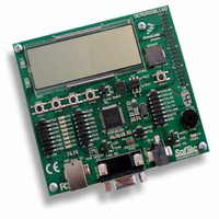
BOARD DEMO FOR 9S08LC60
Manufacturer
Freescale Semiconductor
Type
MCUr
Datasheets
1.DEMO9S08LC60.pdf
(360 pages)
2.DEMO9S08LC60.pdf
(32 pages)
3.DEMO9S08LC60.pdf
(2 pages)
Specifications of DEMO9S08LC60
Contents
Evaluation Board
Processor To Be Evaluated
MC9S08LC60
Interface Type
RS-232, USB
Silicon Manufacturer
Freescale
Core Architecture
HCS08
Core Sub-architecture
HCS08
Silicon Core Number
MC9S08
Silicon Family Name
S08LC
Rohs Compliant
Yes
For Use With/related Products
MC9S08LC60
Lead Free Status / RoHS Status
Lead free / RoHS Compliant


14.4
This section provides a complete functional description of the IIC module.
14.4.1
The IIC bus system uses a serial data line (SDA) and a serial clock line (SCL) for data transfer. All devices
connected to it must have open drain or open collector outputs. A logic AND function is exercised on both
lines with external pull-up resistors. The value of these resistors is system dependent.
Normally, a standard communication is composed of four parts:
The STOP signal should not be confused with the CPU STOP instruction. The IIC bus system
communication is described briefly in the following sections and illustrated in
Freescale Semiconductor
SDA
SCL
SDA
SCL
•
•
•
•
SIGNAL
SIGNAL
START
START
START signal
Slave address transmission
Data transfer
STOP signal
MSB
MSB
AD7 AD6 AD5 AD4 AD3 AD2 AD1 R/W
Functional Description
AD7 AD6 AD5 AD4 AD3 AD2 AD1 R/W
1
1
IIC Protocol
2
2
CALLING ADDRESS
CALLING ADDRESS
3
3
4
4
5
5
MC9S08LC60 Series Data Sheet: Technical Data, Rev. 4
6
6
Figure 14-8. IIC Bus Transmission Signals
7
7
READ/
WRITE
READ/
WRITE
LSB
LSB
8
8
ACK
ACK
BIT
BIT
9
9
XX
REPEATED
SIGNAL
XXX
START
MSB
MSB
AD7 AD6 AD5 AD4 AD3 AD2 AD1 R/W
D7
1
1
D6
2
2
NEW CALLING ADDRESS
D5
3
3
DATA BYTE
D4
4
4
D3
Chapter 14 Inter-Integrated Circuit (S08IICV1)
5
5
D2
6
6
D1
7
7
Figure
READ/
WRITE
LSB
LSB
D0
8
8
ACK
BIT
NO
ACK
NO
BIT
9
9
14-8.
SIGNAL
SIGNAL
STOP
STOP
259
Related parts for DEMO9S08LC60
Image
Part Number
Description
Manufacturer
Datasheet
Request
R

Part Number:
Description:
Manufacturer:
Freescale Semiconductor, Inc
Datasheet:
Part Number:
Description:
Manufacturer:
Freescale Semiconductor, Inc
Datasheet:
Part Number:
Description:
Manufacturer:
Freescale Semiconductor, Inc
Datasheet:
Part Number:
Description:
Manufacturer:
Freescale Semiconductor, Inc
Datasheet:
Part Number:
Description:
Manufacturer:
Freescale Semiconductor, Inc
Datasheet:
Part Number:
Description:
Manufacturer:
Freescale Semiconductor, Inc
Datasheet:
Part Number:
Description:
Manufacturer:
Freescale Semiconductor, Inc
Datasheet:
Part Number:
Description:
Manufacturer:
Freescale Semiconductor, Inc
Datasheet:
Part Number:
Description:
Manufacturer:
Freescale Semiconductor, Inc
Datasheet:
Part Number:
Description:
Manufacturer:
Freescale Semiconductor, Inc
Datasheet:
Part Number:
Description:
Manufacturer:
Freescale Semiconductor, Inc
Datasheet:
Part Number:
Description:
Manufacturer:
Freescale Semiconductor, Inc
Datasheet:
Part Number:
Description:
Manufacturer:
Freescale Semiconductor, Inc
Datasheet:
Part Number:
Description:
Manufacturer:
Freescale Semiconductor, Inc
Datasheet:
Part Number:
Description:
Manufacturer:
Freescale Semiconductor, Inc
Datasheet: