DEMO9S08LC60 Freescale Semiconductor, DEMO9S08LC60 Datasheet - Page 184
DEMO9S08LC60
Manufacturer Part Number
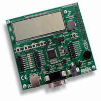
DEMO9S08LC60
Description
BOARD DEMO FOR 9S08LC60
Manufacturer
Freescale Semiconductor
Type
MCUr
Datasheets
1.DEMO9S08LC60.pdf
(360 pages)
2.DEMO9S08LC60.pdf
(32 pages)
3.DEMO9S08LC60.pdf
(2 pages)
Specifications of DEMO9S08LC60
Contents
Evaluation Board
Processor To Be Evaluated
MC9S08LC60
Interface Type
RS-232, USB
Silicon Manufacturer
Freescale
Core Architecture
HCS08
Core Sub-architecture
HCS08
Silicon Core Number
MC9S08
Silicon Family Name
S08LC
Rohs Compliant
Yes
For Use With/related Products
MC9S08LC60
Lead Free Status / RoHS Status
Lead free / RoHS Compliant


Chapter 10 Internal Clock Generator (S08ICGV4)
10.5.7.1 FLL Engaged External Unlocked
FEE unlocked is entered when FEE is entered and the count error (Δn) output from the subtractor is greater
than the maximum n
unlock condition.
The ICG will remain in this state while the count error (Δn) is greater than the maximum n
the minimum n
In this state, the pulse counter, subtractor, digital loop filter, and DCO form a closed loop and attempt to
lock it according to their operational descriptions later in this section. Upon entering this state and until
the FLL becomes locked, the output clock signal ICGOUT frequency is given by f
extra divide by two prevents frequency overshoots during the initial locking process from exceeding
chip-level maximum frequency specifications. After the FLL has locked, if an unexpected loss of lock
causes it to re-enter the unlocked state while the ICG remains in FEE mode, the output clock signal
ICGOUT frequency is given by f
10.5.7.2 FLL Engaged External Locked
FEE locked is entered from FEE unlocked when the count error (Δn) is less than n
than n
condition. The output clock signal ICGOUT frequency is given by f
locked, the filter value is updated only once every four comparison cycles. The update made is an average
of the error measurements taken in the four previous comparisons.
10.5.8
To determine the FLL locked and loss-of-lock conditions, the pulse counter counts the pulses of the DCO
for one comparison cycle (see
to the subtractor. The subtractor compares this value to the value in MFD and produces a count error, Δn.
To achieve locked status, Δn must be between n
must stay between n
unexpectedly, the LOLS status bit is set and remains set until cleared by software or until the MCU is reset.
LOLS is cleared by reading ICGS1 then writing 1 to ICGIF (LOLRE = 0), or by a loss-of-lock induced
reset (LOLRE = 1), or by any MCU reset.
If the ICG enters the off state due to stop mode when ENBDM = OSCSTEN = 0, the FLL loses locked
status (LOCK is cleared), but LOLS remains unchanged because this is not an unexpected loss-of-lock
condition. Though it would be unusual, if ENBDM is cleared to 0 while the MCU is in stop, the ICG enters
the off state. Because this is an unexpected stopping of clocks, LOLS will be set when the MCU wakes up
from stop.
Expected loss of lock occurs when the MFD or CLKS bits are changed or in FEI mode only, when the
TRIM bits are changed. In these cases, the LOCK bit will be cleared until the FLL regains lock, but the
LOLS will not be set.
184
lock
(min) for a given number of samples, as required by the lock detector to detect the lock
FLL Lock and Loss-of-Lock Detection
lock
, as required by the lock detector to detect the lock condition.
unlock
unlock
(min) and n
or less than the minimum n
MC9S08LC60 Series Data Sheet: Technical Data, Rev. 4
Table 10-9
ICGDCLK
unlock
for explanation of a comparison cycle) and passes this number
/ R.
(max) to remain locked. If Δn goes outside this range
lock
(min) and n
unlock
, as required by the lock detector to detect the
lock
ICGDCLK
(max). After the FLL has locked, Δn
/R. In FLL engaged external
ICGDCLK
lock
Freescale Semiconductor
(max) and greater
lock
/ (2×R) This
or less than
Related parts for DEMO9S08LC60
Image
Part Number
Description
Manufacturer
Datasheet
Request
R

Part Number:
Description:
Manufacturer:
Freescale Semiconductor, Inc
Datasheet:
Part Number:
Description:
Manufacturer:
Freescale Semiconductor, Inc
Datasheet:
Part Number:
Description:
Manufacturer:
Freescale Semiconductor, Inc
Datasheet:
Part Number:
Description:
Manufacturer:
Freescale Semiconductor, Inc
Datasheet:
Part Number:
Description:
Manufacturer:
Freescale Semiconductor, Inc
Datasheet:
Part Number:
Description:
Manufacturer:
Freescale Semiconductor, Inc
Datasheet:
Part Number:
Description:
Manufacturer:
Freescale Semiconductor, Inc
Datasheet:
Part Number:
Description:
Manufacturer:
Freescale Semiconductor, Inc
Datasheet:
Part Number:
Description:
Manufacturer:
Freescale Semiconductor, Inc
Datasheet:
Part Number:
Description:
Manufacturer:
Freescale Semiconductor, Inc
Datasheet:
Part Number:
Description:
Manufacturer:
Freescale Semiconductor, Inc
Datasheet:
Part Number:
Description:
Manufacturer:
Freescale Semiconductor, Inc
Datasheet:
Part Number:
Description:
Manufacturer:
Freescale Semiconductor, Inc
Datasheet:
Part Number:
Description:
Manufacturer:
Freescale Semiconductor, Inc
Datasheet:
Part Number:
Description:
Manufacturer:
Freescale Semiconductor, Inc
Datasheet: