DEMO9S08LC60 Freescale Semiconductor, DEMO9S08LC60 Datasheet - Page 67
DEMO9S08LC60
Manufacturer Part Number
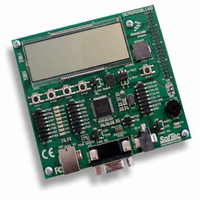
DEMO9S08LC60
Description
BOARD DEMO FOR 9S08LC60
Manufacturer
Freescale Semiconductor
Type
MCUr
Datasheets
1.DEMO9S08LC60.pdf
(360 pages)
2.DEMO9S08LC60.pdf
(32 pages)
3.DEMO9S08LC60.pdf
(2 pages)
Specifications of DEMO9S08LC60
Contents
Evaluation Board
Processor To Be Evaluated
MC9S08LC60
Interface Type
RS-232, USB
Silicon Manufacturer
Freescale
Core Architecture
HCS08
Core Sub-architecture
HCS08
Silicon Core Number
MC9S08
Silicon Family Name
S08LC
Rohs Compliant
Yes
For Use With/related Products
MC9S08LC60
Lead Free Status / RoHS Status
Lead free / RoHS Compliant


5.5.2
External interrupts are managed by the IRQSC status and control register. When the IRQ function is
enabled, synchronous logic monitors the pin for edge-only or edge-and-level events. When the MCU is in
stop mode and system clocks are shut down, a separate asynchronous path is used so the IRQ (if enabled)
can wake the MCU.
5.5.2.1
The IRQ pin enable (IRQPE) control bit in the IRQSC register must be 1 for the IRQ pin to act as the
interrupt request (IRQ) input. When the pin is configured as an IRQ input, the user can choose the polarity
of edges or levels detected (IRQEDG), whether the pin detects edges-only or edges and levels (IRQMOD),
and whether an event causes an interrupt or only sets the IRQF flag (which can be polled by software).
When the IRQ pin is configured to detect rising edges, an optional pulldown resistor is available rather than
a pullup resistor. BIH and BIL instructions may be used to detect the level on the IRQ pin when the pin is
configured to act as the IRQ input.
5.5.2.2
The IRQMOD control bit re-configures the detection logic so it detects edge events and pin levels. In this
edge detection mode, the IRQF status flag becomes set when an edge is detected (when the IRQ pin
changes from the deasserted to the asserted level), but the flag is continuously set (and cannot be cleared)
as long as the IRQ pin remains at the asserted level.
5.5.3
Table 5-2
bottom of the table. The high-order byte of the address for the interrupt service routine is located at the
first address in the vector address column, and the low-order byte of the address for the interrupt service
routine is located at the next higher address.
When an interrupt condition occurs, an associated flag bit becomes set. If the associated local interrupt
enable is 1, an interrupt request is sent to the CPU. Within the CPU, if the global interrupt mask (I bit in
the CCR) is 0, the CPU will finish the current instruction, stack the PCL, PCH, X, A, and CCR CPU
registers, set the I bit, and then fetch the interrupt vector for the highest priority pending interrupt.
Processing then continues in the interrupt service routine.
Freescale Semiconductor
provides a summary of all interrupt sources. Higher-priority sources are located toward the
External Interrupt Request (IRQ) Pin
Interrupt Vectors, Sources, and Local Masks
Pin Configuration Options
Edge and Level Sensitivity
The voltage measured on the pulled up IRQ pin may be as low as
V
to V
measurement of V
DD
DD
– 0.7 V. The internal gates connected to this pin are pulled all the way
. All other pins with enabled pullup resistors will have an unloaded
MC9S08LC60 Series Data Sheet: Technical Data, Rev. 4
DD
.
NOTE
Chapter 5 Resets, Interrupts, and System Configuration
67
Related parts for DEMO9S08LC60
Image
Part Number
Description
Manufacturer
Datasheet
Request
R

Part Number:
Description:
Manufacturer:
Freescale Semiconductor, Inc
Datasheet:
Part Number:
Description:
Manufacturer:
Freescale Semiconductor, Inc
Datasheet:
Part Number:
Description:
Manufacturer:
Freescale Semiconductor, Inc
Datasheet:
Part Number:
Description:
Manufacturer:
Freescale Semiconductor, Inc
Datasheet:
Part Number:
Description:
Manufacturer:
Freescale Semiconductor, Inc
Datasheet:
Part Number:
Description:
Manufacturer:
Freescale Semiconductor, Inc
Datasheet:
Part Number:
Description:
Manufacturer:
Freescale Semiconductor, Inc
Datasheet:
Part Number:
Description:
Manufacturer:
Freescale Semiconductor, Inc
Datasheet:
Part Number:
Description:
Manufacturer:
Freescale Semiconductor, Inc
Datasheet:
Part Number:
Description:
Manufacturer:
Freescale Semiconductor, Inc
Datasheet:
Part Number:
Description:
Manufacturer:
Freescale Semiconductor, Inc
Datasheet:
Part Number:
Description:
Manufacturer:
Freescale Semiconductor, Inc
Datasheet:
Part Number:
Description:
Manufacturer:
Freescale Semiconductor, Inc
Datasheet:
Part Number:
Description:
Manufacturer:
Freescale Semiconductor, Inc
Datasheet:
Part Number:
Description:
Manufacturer:
Freescale Semiconductor, Inc
Datasheet: