DEMO9S08LC60 Freescale Semiconductor, DEMO9S08LC60 Datasheet - Page 162
DEMO9S08LC60
Manufacturer Part Number
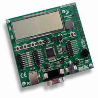
DEMO9S08LC60
Description
BOARD DEMO FOR 9S08LC60
Manufacturer
Freescale Semiconductor
Type
MCUr
Datasheets
1.DEMO9S08LC60.pdf
(360 pages)
2.DEMO9S08LC60.pdf
(32 pages)
3.DEMO9S08LC60.pdf
(2 pages)
Specifications of DEMO9S08LC60
Contents
Evaluation Board
Processor To Be Evaluated
MC9S08LC60
Interface Type
RS-232, USB
Silicon Manufacturer
Freescale
Core Architecture
HCS08
Core Sub-architecture
HCS08
Silicon Core Number
MC9S08
Silicon Family Name
S08LC
Rohs Compliant
Yes
For Use With/related Products
MC9S08LC60
Lead Free Status / RoHS Status
Lead free / RoHS Compliant


Chapter 9 Liquid Crystal Display Driver (S08LCDV1)
9.5.2.4
Example 3 LCD setup requirements are reiterated in the table below:
Table 9-25
162
LCDSUPPLY
FPENR[5:0]
XXXXXX00
0XXX1001
LCDCLKS
1100XX10
0X010X11
00000000
LCDBCTL
Register
LCDCR1
LCDCR0
Example
4
lists the required setup values required to initialize the LCD as specified by Example 4:
Initialization
VSUPPLY[1:0]
CPCADJ[1:0]
CLKADJ[5:0]
Operating
Bit/bit field
BRATE[2:0]
LCDCPMS
BLKMODE
LCDCPEN
HDRVBUF
DUTY[1:0]
Voltage,
BBYPASS
LCDSTP3
LCLK[2:0]
SOURCE
LPWAVE
FPENR0
FPENR1
FPENR2
FPENR3
FPENR4
FPENR5
LCDWAI
1.8-V
DIV16
V
DD
LCD Clock
32.768 kHz
Table 9-25. Initialization Register Values for Example 4
External
Source
XXXXXXX1
MC9S08LC60 Series Data Sheet: Technical Data, Rev. 4
11111111
11111111
11111111
11111111
11111111
000000
Binary
Value
010
001
Example 4
00
10
10
X
X
X
0
0
1
1
0
0
1
LCD Glass
Operating
Voltage
Selects the external clock reference as the LCD clock input
External clock reference = 0; Bus clock = 1
Adjusts the LCD clock input (see table 9-12)
Adjusts the LCD clock input (see table 9-12)
Enable the charge pump
For 3-V LCD glass, select tripler mode
Doubler mode = 0; Tripler mode = 1
High drive buffer
Configure LCD charge pump clock source
Buffer Bypass; Buffer mode = 0; Unbuffered mode = 1
When VSUPPLY[1:0] = 10, the LCD must be externally powered via V
table 9-16). For 5-V glass, the nominal value of V
LCD is “off” in WAIT mode
LCD is “off” in STOP3 mode
For 1/3 duty cycle, select the closest value to the desired 30 Hz LCD frame
frequency (see table 9-13). Note the LCD base frequency - 128.1 Hz
Low power waveform
For 123 segments (3x41), select 1/3 duty cycle (see table 9-11)
Blink all segments; Blink Segments = 0; Blink All = 1
Using the LCD base frequency for the selected LCD frame frequency, select 2.0
Hz blink frequency (see table 9-15).
All 41 LCD frontplanes need to be enabled.
5-V
segments
Required
LCD
123
Frame
30 Hz
Rate
LCD
Comment
all segment
Mode/Rate
Blinking
2.0 Hz
LCD
should be 1.67-V.
WAIT modes
Behavior in
STOP3 and
Freescale Semiconductor
STOP3: off
WAIT: off
LCD
Power
Power
Input
V
LCD
via
LCD
(see
Related parts for DEMO9S08LC60
Image
Part Number
Description
Manufacturer
Datasheet
Request
R

Part Number:
Description:
Manufacturer:
Freescale Semiconductor, Inc
Datasheet:
Part Number:
Description:
Manufacturer:
Freescale Semiconductor, Inc
Datasheet:
Part Number:
Description:
Manufacturer:
Freescale Semiconductor, Inc
Datasheet:
Part Number:
Description:
Manufacturer:
Freescale Semiconductor, Inc
Datasheet:
Part Number:
Description:
Manufacturer:
Freescale Semiconductor, Inc
Datasheet:
Part Number:
Description:
Manufacturer:
Freescale Semiconductor, Inc
Datasheet:
Part Number:
Description:
Manufacturer:
Freescale Semiconductor, Inc
Datasheet:
Part Number:
Description:
Manufacturer:
Freescale Semiconductor, Inc
Datasheet:
Part Number:
Description:
Manufacturer:
Freescale Semiconductor, Inc
Datasheet:
Part Number:
Description:
Manufacturer:
Freescale Semiconductor, Inc
Datasheet:
Part Number:
Description:
Manufacturer:
Freescale Semiconductor, Inc
Datasheet:
Part Number:
Description:
Manufacturer:
Freescale Semiconductor, Inc
Datasheet:
Part Number:
Description:
Manufacturer:
Freescale Semiconductor, Inc
Datasheet:
Part Number:
Description:
Manufacturer:
Freescale Semiconductor, Inc
Datasheet:
Part Number:
Description:
Manufacturer:
Freescale Semiconductor, Inc
Datasheet: