Z8F16800144ZCOG Zilog, Z8F16800144ZCOG Datasheet - Page 194
Z8F16800144ZCOG
Manufacturer Part Number
Z8F16800144ZCOG
Description
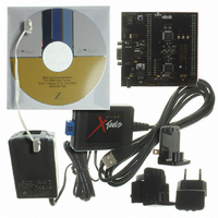
KIT DEV FOR Z8F642 MCU 44 PIN
Manufacturer
Zilog
Series
Z8 Encore!®r
Type
MCUr
Specifications of Z8F16800144ZCOG
Contents
Hardware, Software and Documentation
For Use With/related Products
Z8F642
For Use With
269-4661 - KIT ACC ETHERNET SMART CABLE
Lead Free Status / RoHS Status
Lead free / RoHS Compliant
Other names
269-4678


Infrared Encoder/Decoder Control Register Definitions
PS025011-1010
Caution:
The window remains open until the count again reaches 8 (in other words, 24 baud clock
periods since the previous pulse is detected), giving the Endec a sampling window of
minus 4 baud rate clocks to plus 8 baud rate clocks around the expected time of an
incoming pulse. If an incoming pulse is detected inside this window this process is
repeated. If the incoming data is a logical 1 (no pulse), the Endec returns to the initial state
and waits for the next falling edge. As each falling edge is detected, the Endec clock
counter is reset, resynchronizing the Endec to the incoming signal, allowing the Endec to
tolerate jitter and baud rate errors in the incoming datastream. Resynchronizing the Endec
does not alter the operation of the UART, which ultimately receives the data. The UART is
only synchronized to the incoming data stream when a Start bit is received.
All Infrared Endec configuration and status information is set by the UART control
registers as defined beginning on page 159.
To prevent spurious signals during IrDA data transmission, set the
UART Control 1 register to 1 to enable the Infrared Encoder/Decoder before enabling
the GPIO Port alternate function for the corresponding pin of UART. See
through
Table 17
on pages 52 through 57 for details.
P R E L I M I N A R Y
Z8 Encore! XP
Product Specification
Infrared Encoder/Decoder
IREN
®
F1680 Series
Table 15
bit in the
180
Related parts for Z8F16800144ZCOG
Image
Part Number
Description
Manufacturer
Datasheet
Request
R

Part Number:
Description:
Communication Controllers, ZILOG INTELLIGENT PERIPHERAL CONTROLLER (ZIP)
Manufacturer:
Zilog, Inc.
Datasheet:

Part Number:
Description:
KIT DEV FOR Z8 ENCORE 16K TO 64K
Manufacturer:
Zilog
Datasheet:

Part Number:
Description:
KIT DEV Z8 ENCORE XP 28-PIN
Manufacturer:
Zilog
Datasheet:

Part Number:
Description:
DEV KIT FOR Z8 ENCORE 8K/4K
Manufacturer:
Zilog
Datasheet:

Part Number:
Description:
KIT DEV Z8 ENCORE XP 28-PIN
Manufacturer:
Zilog
Datasheet:

Part Number:
Description:
DEV KIT FOR Z8 ENCORE 4K TO 8K
Manufacturer:
Zilog
Datasheet:
Part Number:
Description:
CMOS Z8 microcontroller. ROM 16 Kbytes, RAM 256 bytes, speed 16 MHz, 32 lines I/O, 3.0V to 5.5V
Manufacturer:
Zilog, Inc.
Datasheet:
Part Number:
Description:
Low-cost microcontroller. 512 bytes ROM, 61 bytes RAM, 8 MHz
Manufacturer:
Zilog, Inc.
Datasheet:
Part Number:
Description:
Z8 4K OTP Microcontroller
Manufacturer:
Zilog, Inc.
Datasheet:
Part Number:
Description:
CMOS SUPER8 ROMLESS MCU
Manufacturer:
Zilog, Inc.
Datasheet:
Part Number:
Description:
SL1866 CMOSZ8 OTP Microcontroller
Manufacturer:
Zilog, Inc.
Datasheet:
Part Number:
Description:
SL1866 CMOSZ8 OTP Microcontroller
Manufacturer:
Zilog, Inc.
Datasheet:
Part Number:
Description:
OTP (KB) = 1, RAM = 125, Speed = 12, I/O = 14, 8-bit Timers = 2, Comm Interfaces Other Features = Por, LV Protect, Voltage = 4.5-5.5V
Manufacturer:
Zilog, Inc.
Datasheet:
Part Number:
Description:
Manufacturer:
Zilog, Inc.
Datasheet: