Z8F16800144ZCOG Zilog, Z8F16800144ZCOG Datasheet - Page 61
Z8F16800144ZCOG
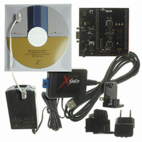
Manufacturer Part Number
Z8F16800144ZCOG
Description
KIT DEV FOR Z8F642 MCU 44 PIN
Manufacturer
Zilog
Series
Z8 Encore!®r
Type
MCUr
Specifications of Z8F16800144ZCOG
Contents
Hardware, Software and Documentation
For Use With/related Products
Z8F642
For Use With
269-4661 - KIT ACC ETHERNET SMART CABLE
Lead Free Status / RoHS Status
Lead free / RoHS Compliant
Other names
269-4678


Table 12. Power Control Register 0 (PWRCTL0)
Power Control Register Definitions
PS025011-1010
BITS
FIELD
RESET
R/W
ADDR
Note:
Power Control Register 0
TRAM
R/W
7
1
Each bit of the following registers disables a peripheral block, either by gating its system
clock input or by removing power from the block.
The default state of the low-power operational amplifier is OFF. To use the low-power
operational amplifier, clear the TRAM bit by turning it ON. Clearing this bit might inter-
fere with normal ADC measurements on ANA0 (the LPO output). This bit enables the
amplifier even in STOP mode. If the amplifier is not required in STOP mode, disable it.
Failure to perform this results in STOP mode currents greater than specified.
This register is only reset during a POR sequence. Other System Reset events do
not affect it.
TRAM— Low-Power Operational Amplifier Disable
0 = Low-Power Operational Amplifier is enabled (this applies even in STOP mode).
1 = Low-Power Operational Amplifier is disabled.
Reserved—Must be 0.
LVD/VBO— Low-Voltage Detection/Voltage Brownout Detector Disable
0 = LVD/VBO Enabled
1 = LVD/VBO Disabled
The LVD and VBO circuits are enabled or disabled separately to minimize power
consumption in low-power modes. The LVD is controlled by the LVD/VBO bit only in all
modes. The VBO is set by the
Program Memory Address 0000H.
and VBO circuits in different operation modes.
TEMP—Temperature Sensor Disable
0 = Temperature Sensor Enabled
1 = Temperature Sensor Disabled
R/W
6
0
Reserved
R/W
5
0
P R E L I M I N A R Y
LVD/VBO
LVD/VBO
R/W
Table 13
4
0
F80H
bit and the
on page 48 lists the setup condition for LVD
TEMP
R/W
3
0
VBO_AO
Reserved
Z8 Encore! XP
R/W
2
0
bit of Flash Option bit at
Product Specification
COMP0
R/W
1
0
®
Low-Power Modes
F1680 Series
COMP1
R/W
0
0
47
Related parts for Z8F16800144ZCOG
Image
Part Number
Description
Manufacturer
Datasheet
Request
R

Part Number:
Description:
Communication Controllers, ZILOG INTELLIGENT PERIPHERAL CONTROLLER (ZIP)
Manufacturer:
Zilog, Inc.
Datasheet:

Part Number:
Description:
KIT DEV FOR Z8 ENCORE 16K TO 64K
Manufacturer:
Zilog
Datasheet:

Part Number:
Description:
KIT DEV Z8 ENCORE XP 28-PIN
Manufacturer:
Zilog
Datasheet:

Part Number:
Description:
DEV KIT FOR Z8 ENCORE 8K/4K
Manufacturer:
Zilog
Datasheet:

Part Number:
Description:
KIT DEV Z8 ENCORE XP 28-PIN
Manufacturer:
Zilog
Datasheet:

Part Number:
Description:
DEV KIT FOR Z8 ENCORE 4K TO 8K
Manufacturer:
Zilog
Datasheet:
Part Number:
Description:
CMOS Z8 microcontroller. ROM 16 Kbytes, RAM 256 bytes, speed 16 MHz, 32 lines I/O, 3.0V to 5.5V
Manufacturer:
Zilog, Inc.
Datasheet:
Part Number:
Description:
Low-cost microcontroller. 512 bytes ROM, 61 bytes RAM, 8 MHz
Manufacturer:
Zilog, Inc.
Datasheet:
Part Number:
Description:
Z8 4K OTP Microcontroller
Manufacturer:
Zilog, Inc.
Datasheet:
Part Number:
Description:
CMOS SUPER8 ROMLESS MCU
Manufacturer:
Zilog, Inc.
Datasheet:
Part Number:
Description:
SL1866 CMOSZ8 OTP Microcontroller
Manufacturer:
Zilog, Inc.
Datasheet:
Part Number:
Description:
SL1866 CMOSZ8 OTP Microcontroller
Manufacturer:
Zilog, Inc.
Datasheet:
Part Number:
Description:
OTP (KB) = 1, RAM = 125, Speed = 12, I/O = 14, 8-bit Timers = 2, Comm Interfaces Other Features = Por, LV Protect, Voltage = 4.5-5.5V
Manufacturer:
Zilog, Inc.
Datasheet:
Part Number:
Description:
Manufacturer:
Zilog, Inc.
Datasheet: