Z8F16800144ZCOG Zilog, Z8F16800144ZCOG Datasheet - Page 198
Z8F16800144ZCOG
Manufacturer Part Number
Z8F16800144ZCOG
Description
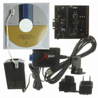
KIT DEV FOR Z8F642 MCU 44 PIN
Manufacturer
Zilog
Series
Z8 Encore!®r
Type
MCUr
Specifications of Z8F16800144ZCOG
Contents
Hardware, Software and Documentation
For Use With/related Products
Z8F642
For Use With
269-4661 - KIT ACC ETHERNET SMART CABLE
Lead Free Status / RoHS Status
Lead free / RoHS Compliant
Other names
269-4678


Table 101. ADC Control Register 0 (ADCCTL0)
ADC Control Register Definitions
PS025011-1010
BITS
FIELD
RESET
R/W
ADDR
Bit Position
[7]
START
[6]
INTREF_SEL
[5]
REFEN
[4]
ADCEN
Internal Voltage Reference Generator
Calibration and Compensation
ADC Control Register 0
START
R/W1
7
0
The Internal Voltage Reference Generator provides the voltage, VR2, for the RBUF.
VR2 is 1.6 V.
You can calibrate and store the values into Flash, or the user code can perform a manual
offset calibration. There is no provision for manual gain calibration.
The ADC Control Registers are described in the following paragraphs.
The ADC Control Register 0 initiates the A/D conversion and provides ADC status
information
Value (H)
0
1
0
1
0
1
0
1
INTREF_SEL
R/W
(Table
6
0
Description
ADC Start/Busy
Writing a 0 has no effect.
Reading a 0 indicates the ADC is available to begin a conversion.
Writing a 1 starts a conversion.
Reading a 1 indicates that a conversion is currently in progress.
Select 1.6 V as internal reference.
Select AVDD as internal reference.
Select external reference.
Select internal reference.
ADC is disabled.
ADC is enabled for normal use. This bit cannot change
with bit 7 (START) at the same time.
101).
REFEN
R/W
5
0
P R E L I M I N A R Y
ADCEN
R/W
4
0
F70h
R/W
3
0
Z8 Encore! XP
R/W
2
0
ANAIN[3:0]
Product Specification
Analog-to-Digital Converter
R/W
1
0
®
F1680 Series
R/W
0
0
184
Related parts for Z8F16800144ZCOG
Image
Part Number
Description
Manufacturer
Datasheet
Request
R

Part Number:
Description:
Communication Controllers, ZILOG INTELLIGENT PERIPHERAL CONTROLLER (ZIP)
Manufacturer:
Zilog, Inc.
Datasheet:

Part Number:
Description:
KIT DEV FOR Z8 ENCORE 16K TO 64K
Manufacturer:
Zilog
Datasheet:

Part Number:
Description:
KIT DEV Z8 ENCORE XP 28-PIN
Manufacturer:
Zilog
Datasheet:

Part Number:
Description:
DEV KIT FOR Z8 ENCORE 8K/4K
Manufacturer:
Zilog
Datasheet:

Part Number:
Description:
KIT DEV Z8 ENCORE XP 28-PIN
Manufacturer:
Zilog
Datasheet:

Part Number:
Description:
DEV KIT FOR Z8 ENCORE 4K TO 8K
Manufacturer:
Zilog
Datasheet:
Part Number:
Description:
CMOS Z8 microcontroller. ROM 16 Kbytes, RAM 256 bytes, speed 16 MHz, 32 lines I/O, 3.0V to 5.5V
Manufacturer:
Zilog, Inc.
Datasheet:
Part Number:
Description:
Low-cost microcontroller. 512 bytes ROM, 61 bytes RAM, 8 MHz
Manufacturer:
Zilog, Inc.
Datasheet:
Part Number:
Description:
Z8 4K OTP Microcontroller
Manufacturer:
Zilog, Inc.
Datasheet:
Part Number:
Description:
CMOS SUPER8 ROMLESS MCU
Manufacturer:
Zilog, Inc.
Datasheet:
Part Number:
Description:
SL1866 CMOSZ8 OTP Microcontroller
Manufacturer:
Zilog, Inc.
Datasheet:
Part Number:
Description:
SL1866 CMOSZ8 OTP Microcontroller
Manufacturer:
Zilog, Inc.
Datasheet:
Part Number:
Description:
OTP (KB) = 1, RAM = 125, Speed = 12, I/O = 14, 8-bit Timers = 2, Comm Interfaces Other Features = Por, LV Protect, Voltage = 4.5-5.5V
Manufacturer:
Zilog, Inc.
Datasheet:
Part Number:
Description:
Manufacturer:
Zilog, Inc.
Datasheet: