PNX1311EH/G,557 NXP Semiconductors, PNX1311EH/G,557 Datasheet - Page 251
PNX1311EH/G,557
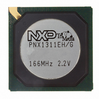
Manufacturer Part Number
PNX1311EH/G,557
Description
IC MEDIA PROC 166MHZ 292-HBGA
Manufacturer
NXP Semiconductors
Datasheet
1.PNX1300EHG557.pdf
(549 pages)
Specifications of PNX1311EH/G,557
Applications
Multimedia
Core Processor
TriMedia
Controller Series
Nexperia
Ram Size
48K x 8
Interface
I²C, 2-Wire Serial
Number Of I /o
169
Voltage - Supply
2.375 V ~ 2.625 V
Operating Temperature
0°C ~ 85°C
Mounting Type
Surface Mount
Package / Case
292-HBGA
Lead Free Status / RoHS Status
Lead free / RoHS Compliant
Program Memory Type
-
Other names
568-1295
935277721557
PNX1311EH/G
935277721557
PNX1311EH/G


Philips Semiconductors
16.5
I
ware I
case, the SCL and SDA pins are fully controlled and ob-
served by software, and the hardware I
disconnected from the SCL and SDA pins. Refer to
Figure 16-3
Software mode is by default disabled after boot. Soft-
ware
IIC_CR.SW_MODE_EN. At that point, the SCL and SDA
pins can be controlled by the IIC_CR SDA_OUT and
SCL_OUT bits. Writing a ‘1’ to either bit causes the cor-
responding pin to become active, i.e. be pulled low. The
SDA and SCL lines are open-collector outputs, and can
hence also be pulled low by external devices. The actual
pin state can be observed by software by examining
IIC_SR SDA_STAT and SCL_STAT bits. A 1 in these
MMIO bits indicates that the corresponding pin is cur-
rently pulled low.
2
Figure 16-3. I
C software operation mode is intended for use by soft-
ENABLE bit effectively resets the entire I
including all status and interrupt flag bits. A transfer
in progress is aborted and the byte currently trans-
ferred is lost.
Note: For writes, Reserved1, 2, 3 and 4 bitfields
MUST always be written with ‘0’s.
2
C or similar algorithm implementations. In this
mode
I
hardware
2
I2C
C SOFTWARE OPERATION MODE
for a clarification of the principles involved.
2
is
C software mode only logic
enabled
HIWAY
by
DATA
writing
2
C interface is
2
C interface,
a
‘1’
scl_out
sda_out
sda_stat
scl_stat
D Q
D Q
tribuf
tribuf
to
sw_mode_en
sw_mode_en
By appropriate software, possibly using a timer interrupt,
full I
mechanism.
16.6
Hardware operation of I
The PNX1300 I
two modes:
1. Master-transmitter (to write data to a slave)
2. Master-receiver (to read data from a slave)
As a master, the I
pulses and the START and STOP bus conditions. The
START and STOP bus conditions are shown in
Figure
or a repeated START condition. Since a repeated
START condition is also the beginning of the next serial
transfer, the I
Note: The I
master ONLY!
The number of bytes transferred between the START
and STOP conditions from transmitter to receiver is not
limited. Each 8-bit data byte is followed by one acknowl-
edge bit. The transmitter releases the SDA line which will
pull-up to a HIGH level during the acknowledge bit time.
The receiver acknowledges by pulling the data line LOW
PRELIMINARY SPECIFICATION
2
C functionality can be implemented using this
16-4. A transfer is ended with a STOP condition
I
2
C HARDWARE OPERATION MODE
open drain
open drain
2
C interface on PNX1300 will operate as a
2
C bus will not be released.
buf
buf
2
C hardware interface operates in one of
2
C logic will generate all the serial clock
2
C is the default mode after boot.
SCL
SDA
I2C Interface
16-5
Related parts for PNX1311EH/G,557
Image
Part Number
Description
Manufacturer
Datasheet
Request
R

Part Number:
Description:
Manufacturer:
NXP Semiconductors
Datasheet:
Part Number:
Description:
Manufacturer:
NXP Semiconductors
Datasheet:

Part Number:
Description:
Video ICs NEXPERIA MEDIA PROCESSOR
Manufacturer:
NXP Semiconductors
Part Number:
Description:
NXP Semiconductors designed the LPC2420/2460 microcontroller around a 16-bit/32-bitARM7TDMI-S CPU core with real-time debug interfaces that include both JTAG andembedded trace
Manufacturer:
NXP Semiconductors
Datasheet:

Part Number:
Description:
NXP Semiconductors designed the LPC2458 microcontroller around a 16-bit/32-bitARM7TDMI-S CPU core with real-time debug interfaces that include both JTAG andembedded trace
Manufacturer:
NXP Semiconductors
Datasheet:
Part Number:
Description:
NXP Semiconductors designed the LPC2468 microcontroller around a 16-bit/32-bitARM7TDMI-S CPU core with real-time debug interfaces that include both JTAG andembedded trace
Manufacturer:
NXP Semiconductors
Datasheet:
Part Number:
Description:
NXP Semiconductors designed the LPC2470 microcontroller, powered by theARM7TDMI-S core, to be a highly integrated microcontroller for a wide range ofapplications that require advanced communications and high quality graphic displays
Manufacturer:
NXP Semiconductors
Datasheet:
Part Number:
Description:
NXP Semiconductors designed the LPC2478 microcontroller, powered by theARM7TDMI-S core, to be a highly integrated microcontroller for a wide range ofapplications that require advanced communications and high quality graphic displays
Manufacturer:
NXP Semiconductors
Datasheet:
Part Number:
Description:
The Philips Semiconductors XA (eXtended Architecture) family of 16-bit single-chip microcontrollers is powerful enough to easily handle the requirements of high performance embedded applications, yet inexpensive enough to compete in the market for hi
Manufacturer:
NXP Semiconductors
Datasheet:
Part Number:
Description:
The XA-S3 device is a member of Philips Semiconductors? XA(eXtended Architecture) family of high performance 16-bitsingle-chip microcontrollers
Manufacturer:
NXP Semiconductors
Datasheet:

Part Number:
Description:
The NXP BlueStreak LH75401/LH75411 family consists of two low-cost 16/32-bit System-on-Chip (SoC) devices
Manufacturer:
NXP Semiconductors
Datasheet:
Part Number:
Description:
The NXP LPC3130/3131 combine an 180 MHz ARM926EJ-S CPU core, high-speed USB2
Manufacturer:
NXP Semiconductors
Datasheet:
Part Number:
Description:
The NXP LPC3141 combine a 270 MHz ARM926EJ-S CPU core, High-speed USB 2
Manufacturer:
NXP Semiconductors
Part Number:
Description:
The NXP LPC3143 combine a 270 MHz ARM926EJ-S CPU core, High-speed USB 2
Manufacturer:
NXP Semiconductors