AT91CAP7E-NA-ZJ Atmel, AT91CAP7E-NA-ZJ Datasheet - Page 468
AT91CAP7E-NA-ZJ
Manufacturer Part Number
AT91CAP7E-NA-ZJ
Description
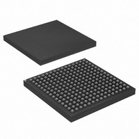
MCU CAP7 FPGA 225LFBGA
Manufacturer
Atmel
Series
CAP™r
Specifications of AT91CAP7E-NA-ZJ
Core Processor
ARM7
Core Size
16/32-Bit
Speed
80MHz
Connectivity
EBI/EMI, FPGA, IrDA, SPI, UART/USART, USB
Peripherals
DMA, POR, PWM, WDT
Number Of I /o
32
Program Memory Size
256KB (256K x 8)
Program Memory Type
ROM
Ram Size
160K x 8
Voltage - Supply (vcc/vdd)
1.08 V ~ 1.32 V
Data Converters
A/D 8x10b
Oscillator Type
Internal
Operating Temperature
-40°C ~ 85°C
Package / Case
225-LFBGA
Processor Series
AT91Mx
Core
ARM7TDMI
Data Bus Width
32 bit
3rd Party Development Tools
JTRACE-ARM-2M, MDK-ARM, RL-ARM, ULINK2
Lead Free Status / RoHS Status
Lead free / RoHS Compliant
Eeprom Size
-
Lead Free Status / Rohs Status
Details
Available stocks
Company
Part Number
Manufacturer
Quantity
Price


32.3
Table 32-1.
32.4
32.4.1
32.4.2
32.4.3
32.4.4
32.4.5
32.4.6
32.5
32.5.1
468
Pin Name
AVDD
ADVREF
AD0 -
ADTRG
AD7
Signal Description
Product Dependencies
Functional Description
AT91CAP7E
Power Management
Interrupt Sources
Analog Inputs
I/O Lines
Timer Triggers
Conversion Performances
Analog-to-digital Conversion
ADC Pin Description
The ADC is automatically clocked after the first conversion in Normal Mode. In Sleep Mode, the
ADC clock is automatically stopped after each conversion. As the logic is small and the ADC cell
can be put into Sleep Mode, the Power Management Controller has no effect on the ADC
behavior.
The ADC interrupt line is connected on one of the internal sources of the Advanced Interrupt
Controller. Using the ADC interrupt requires the AIC to be programmed first.
The analog input pins can be multiplexed with PIO lines. In this case, the assignment of the ADC
input is automatically done as soon as the corresponding channel is enabled by writing the reg-
ister ADC_CHER. By default, after reset, the PIO line is configured as input with its pull-up
enabled and the ADC input is connected to the GND.
The pin ADTRG may be shared with other peripheral functions through the PIO Controller. In
this case, the PIO Controller should be set accordingly to assign the pin ADTRG to the ADC
function.
Timer Counters may or may not be used as hardware triggers depending on user requirements.
Thus, some or all of the timer counters may be non-connected.
For performance and electrical characteristics of the ADC, see the DC Characteristics section.
The ADC uses the ADC Clock to perform conversions. Converting a single analog value to a 10-
bit digital data requires Sample and Hold Clock cycles as defined in the field SHTIM of the
Mode Register” on page 474
the PRESCAL field of the Mode Register (ADC_MR).
Description
Analog power supply
Reference voltage
Analog input channels
External trigger
and 10 ADC Clock cycles. The ADC Clock frequency is selected in
8549A–CAP–10/08
“ADC
Related parts for AT91CAP7E-NA-ZJ
Image
Part Number
Description
Manufacturer
Datasheet
Request
R

Part Number:
Description:
Customizable Microcontroller
Manufacturer:
ATMEL Corporation
Datasheet:

Part Number:
Description:
DEV KIT FOR AVR/AVR32
Manufacturer:
Atmel
Datasheet:
Part Number:
Description:
INTERVAL AND WIPE/WASH WIPER CONTROL IC WITH DELAY
Manufacturer:
ATMEL Corporation
Datasheet:
Part Number:
Description:
Low-Voltage Voice-Switched IC for Hands-Free Operation
Manufacturer:
ATMEL Corporation
Datasheet:
Part Number:
Description:
MONOLITHIC INTEGRATED FEATUREPHONE CIRCUIT
Manufacturer:
ATMEL Corporation
Datasheet:
Part Number:
Description:
AM-FM Receiver IC U4255BM-M
Manufacturer:
ATMEL Corporation
Datasheet:
Part Number:
Description:
Monolithic Integrated Feature Phone Circuit
Manufacturer:
ATMEL Corporation
Datasheet:
Part Number:
Description:
Multistandard Video-IF and Quasi Parallel Sound Processing
Manufacturer:
ATMEL Corporation
Datasheet:
Part Number:
Description:
High-performance EE PLD
Manufacturer:
ATMEL Corporation
Datasheet:
Part Number:
Description:
8-bit Flash Microcontroller
Manufacturer:
ATMEL Corporation
Datasheet:
Part Number:
Description:
2-Wire Serial EEPROM
Manufacturer:
ATMEL Corporation
Datasheet: