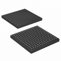
AT91CAP7E-NA-ZJ Atmel, AT91CAP7E-NA-ZJ Datasheet - Page 471

AT91CAP7E-NA-ZJ
Manufacturer Part Number
AT91CAP7E-NA-ZJ
Description
MCU CAP7 FPGA 225LFBGA
Manufacturer
Atmel
Series
CAP™r
Specifications of AT91CAP7E-NA-ZJ
Core Processor
ARM7
Core Size
16/32-Bit
Speed
80MHz
Connectivity
EBI/EMI, FPGA, IrDA, SPI, UART/USART, USB
Peripherals
DMA, POR, PWM, WDT
Number Of I /o
32
Program Memory Size
256KB (256K x 8)
Program Memory Type
ROM
Ram Size
160K x 8
Voltage - Supply (vcc/vdd)
1.08 V ~ 1.32 V
Data Converters
A/D 8x10b
Oscillator Type
Internal
Operating Temperature
-40°C ~ 85°C
Package / Case
225-LFBGA
Processor Series
AT91Mx
Core
ARM7TDMI
Data Bus Width
32 bit
3rd Party Development Tools
JTRACE-ARM-2M, MDK-ARM, RL-ARM, ULINK2
Lead Free Status / RoHS Status
Lead free / RoHS Compliant
Eeprom Size
-
Lead Free Status / Rohs Status
Details
Available stocks
Company
Part Number
Manufacturer
Quantity
Price
- Current page: 471 of 520
- Download datasheet (11Mb)
Figure 32-3. GOVRE and OVREx Flag Behavior
32.5.5
8549A–CAP–10/08
(ADC_CHSR)
(ADC_CHSR)
ADC_LCDR
ADC_CDR0
ADC_CDR1
(ADC_SR)
(ADC_SR)
(ADC_SR)
(ADC_SR)
(ADC_SR)
GOVRE
ADTRG
DRDY
OVRE0
EOC0
EOC1
Conversion Triggers
CH0
CH1
Undefined Data
Undefined Data
Warning: If the corresponding channel is disabled during a conversion or if it is disabled and
then reenabled during a conversion, its associated data and its corresponding EOC and OVRE
flags in ADC_SR are unpredictable.
Conversions of the active analog channels are started with a software or a hardware trigger. The
software trigger is provided by writing the Control Register (ADC_CR) with the bit START at 1.
The hardware trigger can be one of the TIOA outputs of the Timer Counter channels, or the
external trigger input of the ADC (ADTRG). The hardware trigger is selected with the field TRG-
SEL in the Mode Register (ADC_MR). The selected hardware trigger is enabled with the bit
TRGEN in the Mode Register (ADC_MR).
If a hardware trigger is selected, the start of a conversion is detected at each rising edge of the
selected signal. If one of the TIOA outputs is selected, the corresponding Timer Counter channel
must be programmed in Waveform Mode.
Conversion
Undefined Data
Conversion
Data A
Data A
Data B
Conversion
Data B
Data C
Read ADC_CDR1
Data C
AT91CAP7E
Read ADC_SR
Read ADC_CDR0
471
Related parts for AT91CAP7E-NA-ZJ
Image
Part Number
Description
Manufacturer
Datasheet
Request
R

Part Number:
Description:
Customizable Microcontroller
Manufacturer:
ATMEL Corporation
Datasheet:

Part Number:
Description:
DEV KIT FOR AVR/AVR32
Manufacturer:
Atmel
Datasheet:

Part Number:
Description:
INTERVAL AND WIPE/WASH WIPER CONTROL IC WITH DELAY
Manufacturer:
ATMEL Corporation
Datasheet:

Part Number:
Description:
Low-Voltage Voice-Switched IC for Hands-Free Operation
Manufacturer:
ATMEL Corporation
Datasheet:

Part Number:
Description:
MONOLITHIC INTEGRATED FEATUREPHONE CIRCUIT
Manufacturer:
ATMEL Corporation
Datasheet:

Part Number:
Description:
AM-FM Receiver IC U4255BM-M
Manufacturer:
ATMEL Corporation
Datasheet:

Part Number:
Description:
Monolithic Integrated Feature Phone Circuit
Manufacturer:
ATMEL Corporation
Datasheet:

Part Number:
Description:
Multistandard Video-IF and Quasi Parallel Sound Processing
Manufacturer:
ATMEL Corporation
Datasheet:

Part Number:
Description:
High-performance EE PLD
Manufacturer:
ATMEL Corporation
Datasheet:

Part Number:
Description:
8-bit Flash Microcontroller
Manufacturer:
ATMEL Corporation
Datasheet:

Part Number:
Description:
2-Wire Serial EEPROM
Manufacturer:
ATMEL Corporation
Datasheet:


