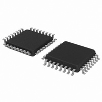
C8051F930-GQ Silicon Laboratories Inc, C8051F930-GQ Datasheet - Page 5

C8051F930-GQ
Manufacturer Part Number
C8051F930-GQ
Description
IC 8051 MCU 64K FLASH 32-LQFP
Manufacturer
Silicon Laboratories Inc
Series
C8051F9xxr
Specifications of C8051F930-GQ
Program Memory Type
FLASH
Program Memory Size
64KB (64K x 8)
Package / Case
32-LQFP
Core Processor
8051
Core Size
8-Bit
Speed
25MHz
Connectivity
SMBus (2-Wire/I²C), SPI, UART/USART
Peripherals
Brown-out Detect/Reset, POR, PWM, Temp Sensor, WDT
Number Of I /o
24
Ram Size
4.25K x 8
Voltage - Supply (vcc/vdd)
0.9 V ~ 3.6 V
Data Converters
A/D 23x10b
Oscillator Type
Internal
Operating Temperature
-40°C ~ 85°C
Processor Series
C8051F9x
Core
8051
Data Bus Width
8 bit
Data Ram Size
4.25 KB
Interface Type
I2C/SMBus/SPI/UART
Maximum Clock Frequency
25 MHz
Number Of Programmable I/os
24
Number Of Timers
4
Operating Supply Voltage
0.9 V to 3.6 V
Maximum Operating Temperature
+ 85 C
Mounting Style
SMD/SMT
3rd Party Development Tools
PK51, CA51, A51, ULINK2
Development Tools By Supplier
C8051F930DK
Minimum Operating Temperature
- 40 C
On-chip Adc
23-ch x 10-bit
No. Of I/o's
24
Ram Memory Size
4KB
Cpu Speed
25MHz
No. Of Timers
4
Rohs Compliant
Yes
Lead Free Status / RoHS Status
Lead free / RoHS Compliant
For Use With
336-1478 - PLATFORM PROG TOOLSTCK F920,F930336-1477 - PLATFORM PROG TOOLSTCK F920,F930336-1473 - KIT DEV C8051F920,F921,F930,F931336-1472 - BOARD TARGET/PROTO W/C8051F930
Eeprom Size
-
Lead Free Status / Rohs Status
Lead free / RoHS Compliant
Other names
336-1466
Available stocks
Company
Part Number
Manufacturer
Quantity
Price
Company:
Part Number:
C8051F930-GQ
Manufacturer:
SILICON
Quantity:
3 500
Company:
Part Number:
C8051F930-GQ
Manufacturer:
Silicon Laboratories Inc
Quantity:
10 000
Company:
Part Number:
C8051F930-GQR
Manufacturer:
Silicon Laboratories Inc
Quantity:
10 000
Part Number:
C8051F930-GQR
Manufacturer:
SILICON LABS/èٹ¯ç§‘
Quantity:
20 000
14. Power Management.............................................................................................. 156
15. Cyclic Redundancy Check Unit (CRC0) ............................................................. 164
16. On-Chip DC-DC Converter (DC0) ........................................................................ 171
17. Voltage Regulator (VREG0) ................................................................................. 179
18. Reset Sources....................................................................................................... 180
13.2.Non-volatile Data Storage .............................................................................. 147
13.3.Security Options ............................................................................................. 147
13.4.Determining the Device Part Number at Run Time ........................................ 149
13.5.Flash Write and Erase Guidelines .................................................................. 150
13.6.Minimizing Flash Read Current ...................................................................... 152
14.1.Normal Mode .................................................................................................. 157
14.2.Idle Mode........................................................................................................ 158
14.3.Stop Mode ...................................................................................................... 158
14.4.Suspend Mode ............................................................................................... 159
14.5.Sleep Mode .................................................................................................... 159
14.6.Configuring Wakeup Sources......................................................................... 160
14.7.Determining the Event that Caused the Last Wakeup.................................... 161
14.8.Power Management Specifications ................................................................ 163
15.1.CRC Algorithm................................................................................................ 164
15.2.Preparing for a CRC Calculation .................................................................... 166
15.3.Performing a CRC Calculation ....................................................................... 166
15.4.Accessing the CRC0 Result ........................................................................... 166
15.5.CRC0 Bit Reverse Feature............................................................................. 170
16.1.Startup Behavior............................................................................................. 172
16.2.High Power Applications................................................................................. 173
16.3.Pulse Skipping Mode...................................................................................... 173
16.4.Enabling the DC-DC Converter ...................................................................... 174
16.5.Minimizing Power Supply Noise ..................................................................... 175
16.6.Selecting the Optimum Switch Size................................................................ 175
16.7.DC-DC Converter Clocking Options ............................................................... 175
16.8.DC-DC Converter Behavior in Sleep Mode .................................................... 175
16.9.DC-DC Converter Register Descriptions ........................................................ 177
16.10.DC-DC Converter Specifications .................................................................. 178
17.1.Voltage Regulator Electrical Specifications .................................................... 179
18.1.Power-On (VBAT Supply Monitor) Reset ....................................................... 181
18.2.Power-Fail (VDD/DC+ Supply Monitor) Reset................................................ 182
18.3.External Reset ................................................................................................ 184
18.4.Missing Clock Detector Reset ........................................................................ 184
18.5.Comparator0 Reset ........................................................................................ 184
18.6.PCA Watchdog Timer Reset .......................................................................... 184
18.7.Flash Error Reset ........................................................................................... 185
13.1.3.Flash Write Procedure ........................................................................... 146
13.5.1.VDD Maintenance and the VDD Monitor ............................................... 150
13.5.2.PSWE Maintenance ............................................................................... 151
13.5.3.System Clock ......................................................................................... 151
Rev. 1.1
C8051F93x-C8051F92x
5


