DF38602RFT10 Renesas Electronics America, DF38602RFT10 Datasheet - Page 110
DF38602RFT10
Manufacturer Part Number
DF38602RFT10
Description
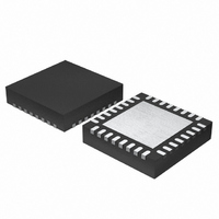
MCU 3V 16K 32-QFN
Manufacturer
Renesas Electronics America
Series
H8® H8/300H SLPr
Datasheet
1.DF38602RFT10.pdf
(554 pages)
Specifications of DF38602RFT10
Core Processor
H8/300H
Core Size
16-Bit
Speed
10MHz
Connectivity
I²C, IrDA, SCI, SSU
Peripherals
POR, PWM, WDT
Number Of I /o
13
Program Memory Size
16KB (16K x 8)
Program Memory Type
FLASH
Ram Size
1K x 8
Voltage - Supply (vcc/vdd)
2.7 V ~ 3.6 V
Data Converters
A/D 6x10b
Oscillator Type
Internal
Operating Temperature
-20°C ~ 75°C
Package / Case
32-QFN
Lead Free Status / RoHS Status
Contains lead / RoHS non-compliant
Eeprom Size
-
Other names
HD64F38602RFT10
HD64F38602RFT10
HD64F38602RFT10
Available stocks
Company
Part Number
Manufacturer
Quantity
Price
Company:

Part Number:
DF38602RFT10V
Manufacturer:
Renesas Electronics America
Quantity:
135


Section 4 Clock Pulse Generators
4.5.4
To stop the subclock, a state transition should not be made except to mode in which the system
clock operates. If the state transition is made to other mode, it may result in incorrect operation.
4.5.5
When a microcomputer operates, the internal power supply potential fluctuates slightly in
synchronization with the system clock. Depending on the individual resonator characteristics, the
oscillation waveform amplitude may not be sufficiently large immediately after the oscillation
stabilization wait time, making the oscillation waveform susceptible to influence by fluctuations in
the power supply potential. In this state, the oscillation waveform may be disrupted, leading to an
unstable system clock and incorrect operation of the microcomputer.
If incorrect operation occurs, change the setting of the standby timer select bits 2 to 0 (STS2 to
STS0) (bits 6 to 4 in the system control register 1 (SYSCR1)) to give a longer wait time.
For example, if incorrect operation occurs with a wait time setting of 512 states, check the
operation with a wait time setting of 1,024 states or more.
If the same kind of incorrect operation occurs after a reset as after a state transition, hold the RES
pin low for a longer period.
4.5.6
The power-on reset circuit in this LSI adjusts the reset clear time by the capacitor capacitance,
which is externally connected to the RES pin. The external capacitor capacitance should be
adjusted to secure the oscillation stabilization time before reset clearing. For details, refer to
section 19, Power-On Reset Circuit.
4.5.7
When the on-chip emulator is used, system clock accuracy is necessary for flash memory
programming/erasing. The frequency of the on-chip oscillator differs depending on the voltage
and temperature conditions. Therefore, when using the on-chip emulator, the resonator must be
connected to the OSC1 and OSC2 pins or an external clock must be supplied. In this case, the on-
chip oscillator is used for user program execution, and the system clock is used for flash memory
programming/erasing. This control is handled when the E7_2 pin is fixed to high level during a
reset by the on-chip emulator.
Rev. 3.00 May 15, 2007 Page 76 of 516
REJ09B0152-0300
Note on Subclock Stop State
Note on the Oscillation Stabilization of Resonators
Note on Using Power-On Reset
Note on Using On-Chip Emulator
Related parts for DF38602RFT10
Image
Part Number
Description
Manufacturer
Datasheet
Request
R

Part Number:
Description:
KIT STARTER FOR M16C/29
Manufacturer:
Renesas Electronics America
Datasheet:

Part Number:
Description:
KIT STARTER FOR R8C/2D
Manufacturer:
Renesas Electronics America
Datasheet:

Part Number:
Description:
R0K33062P STARTER KIT
Manufacturer:
Renesas Electronics America
Datasheet:

Part Number:
Description:
KIT STARTER FOR R8C/23 E8A
Manufacturer:
Renesas Electronics America
Datasheet:

Part Number:
Description:
KIT STARTER FOR R8C/25
Manufacturer:
Renesas Electronics America
Datasheet:

Part Number:
Description:
KIT STARTER H8S2456 SHARPE DSPLY
Manufacturer:
Renesas Electronics America
Datasheet:

Part Number:
Description:
KIT STARTER FOR R8C38C
Manufacturer:
Renesas Electronics America
Datasheet:

Part Number:
Description:
KIT STARTER FOR R8C35C
Manufacturer:
Renesas Electronics America
Datasheet:

Part Number:
Description:
KIT STARTER FOR R8CL3AC+LCD APPS
Manufacturer:
Renesas Electronics America
Datasheet:
Part Number:
Description:
KIT STARTER FOR RX610
Manufacturer:
Renesas Electronics America
Datasheet:

Part Number:
Description:
KIT STARTER FOR R32C/118
Manufacturer:
Renesas Electronics America
Datasheet:

Part Number:
Description:
KIT DEV RSK-R8C/26-29
Manufacturer:
Renesas Electronics America
Datasheet:

Part Number:
Description:
KIT STARTER FOR SH7124
Manufacturer:
Renesas Electronics America
Datasheet:

Part Number:
Description:
KIT STARTER FOR H8SX/1622
Manufacturer:
Renesas Electronics America
Datasheet:

Part Number:
Description:
KIT DEV FOR SH7203
Manufacturer:
Renesas Electronics America
Datasheet: