DF38602RFT10 Renesas Electronics America, DF38602RFT10 Datasheet - Page 216
DF38602RFT10
Manufacturer Part Number
DF38602RFT10
Description
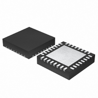
MCU 3V 16K 32-QFN
Manufacturer
Renesas Electronics America
Series
H8® H8/300H SLPr
Datasheet
1.DF38602RFT10.pdf
(554 pages)
Specifications of DF38602RFT10
Core Processor
H8/300H
Core Size
16-Bit
Speed
10MHz
Connectivity
I²C, IrDA, SCI, SSU
Peripherals
POR, PWM, WDT
Number Of I /o
13
Program Memory Size
16KB (16K x 8)
Program Memory Type
FLASH
Ram Size
1K x 8
Voltage - Supply (vcc/vdd)
2.7 V ~ 3.6 V
Data Converters
A/D 6x10b
Oscillator Type
Internal
Operating Temperature
-20°C ~ 75°C
Package / Case
32-QFN
Lead Free Status / RoHS Status
Contains lead / RoHS non-compliant
Eeprom Size
-
Other names
HD64F38602RFT10
HD64F38602RFT10
HD64F38602RFT10
Available stocks
Company
Part Number
Manufacturer
Quantity
Price
Company:

Part Number:
DF38602RFT10V
Manufacturer:
Renesas Electronics America
Quantity:
135


Section 10 Timer W
5. When an input capture function is specified, inputting a valid edge to the FTIOA to FTIOD
6. When the input capture timing conflicts with the corresponding GRA to GRD write timing,
7. When the input capture timing conflicts with the GRA to GRD read timing, the read values are
8. When the input capture A or B conflicts with the GRC or GRD write timing as the input
9. When the compare match timing conflicts with the GRA to GRD write timing as the compare
10. When the compare match A or B conflicts with the GRA or GRB write timing as the compare
11. When the compare match A or B conflicts with the GRC or GRD write timing as the compare
12. When GRC or GRD is specified to the compare match output as the compare match operation
13. When φw, φw/4, φw/16, or FTCI input is selected as the count clock, counting is enabled even
14. When φw, φw/4, φw/16, or FTCI input is selected as the count clock, counting is enabled in
Rev. 3.00 May 15, 2007 Page 182 of 516
REJ09B0152-0300
pins sets the status bit of the corresponding TSRW, even if the CTS bit in TMRW is 0
(counting disabled state). When the relevant interrupt is enabled, this inputting generates an
interrupt.
a. the written values are reflected in GRA to GRD.
b. the status flag of the corresponding TSRW is set.
ones before capturing. The captured values can be read one clock after the capturing.
capture operation in buffer mode,
a. the captured values are reflected in GRA or GRB.
b. the written values are reflected in GRC or GRD. (The values in GRC or GRD are not ones
match operation,
a. the written values are reflected in GRA to GRD.
b. the FTIOA to FTIOD output changes by the compare match.
match operation in buffer mode,
a. the written values are reflected in GRA or GRB. (The values in GRA or GRB are not ones
b. the FTIOA or FTIOB output changes by the compare match.
match operation in buffer mode,
a. the values in GRA or GRB are ones in GRC or GRD before writing.
b. the FTIOA or FTIOB output changes by the compare match.
in buffer mode, FTIOC or FTIOD output changes by the GRC or GRD compare match.
in subactive and subsleep modes. Counting is disabled during the oscillation stabilization time
in transition to the active mode.
active and sleep modes although counting may be misaligned by one in transition from the
active to subactive mode.
in GRA or GRB before capturing.)
in GRC or GRD of the buffer register.)
Related parts for DF38602RFT10
Image
Part Number
Description
Manufacturer
Datasheet
Request
R

Part Number:
Description:
KIT STARTER FOR M16C/29
Manufacturer:
Renesas Electronics America
Datasheet:

Part Number:
Description:
KIT STARTER FOR R8C/2D
Manufacturer:
Renesas Electronics America
Datasheet:

Part Number:
Description:
R0K33062P STARTER KIT
Manufacturer:
Renesas Electronics America
Datasheet:

Part Number:
Description:
KIT STARTER FOR R8C/23 E8A
Manufacturer:
Renesas Electronics America
Datasheet:

Part Number:
Description:
KIT STARTER FOR R8C/25
Manufacturer:
Renesas Electronics America
Datasheet:

Part Number:
Description:
KIT STARTER H8S2456 SHARPE DSPLY
Manufacturer:
Renesas Electronics America
Datasheet:

Part Number:
Description:
KIT STARTER FOR R8C38C
Manufacturer:
Renesas Electronics America
Datasheet:

Part Number:
Description:
KIT STARTER FOR R8C35C
Manufacturer:
Renesas Electronics America
Datasheet:

Part Number:
Description:
KIT STARTER FOR R8CL3AC+LCD APPS
Manufacturer:
Renesas Electronics America
Datasheet:
Part Number:
Description:
KIT STARTER FOR RX610
Manufacturer:
Renesas Electronics America
Datasheet:

Part Number:
Description:
KIT STARTER FOR R32C/118
Manufacturer:
Renesas Electronics America
Datasheet:

Part Number:
Description:
KIT DEV RSK-R8C/26-29
Manufacturer:
Renesas Electronics America
Datasheet:

Part Number:
Description:
KIT STARTER FOR SH7124
Manufacturer:
Renesas Electronics America
Datasheet:

Part Number:
Description:
KIT STARTER FOR H8SX/1622
Manufacturer:
Renesas Electronics America
Datasheet:

Part Number:
Description:
KIT DEV FOR SH7203
Manufacturer:
Renesas Electronics America
Datasheet: