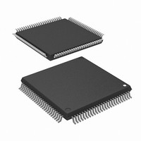
M30624FGNGP#D5 Renesas Electronics America, M30624FGNGP#D5 Datasheet - Page 46

M30624FGNGP#D5
Manufacturer Part Number
M30624FGNGP#D5
Description
IC M16C MCU FLASH 256K 100LQFP
Manufacturer
Renesas Electronics America
Series
M16C™ M16C/60r
Datasheet
1.M30620FCNGPU5.pdf
(250 pages)
Specifications of M30624FGNGP#D5
Core Processor
M16C/60
Core Size
16-Bit
Speed
16MHz
Connectivity
SIO, UART/USART
Peripherals
DMA, PWM, WDT
Number Of I /o
85
Program Memory Size
256KB (256K x 8)
Program Memory Type
FLASH
Ram Size
20K x 8
Voltage - Supply (vcc/vdd)
3 V ~ 3.6 V
Data Converters
A/D 18x10b, D/A 2x8b
Oscillator Type
Internal
Operating Temperature
-20°C ~ 85°C
Package / Case
100-LQFP
Lead Free Status / RoHS Status
Contains lead / RoHS non-compliant
Eeprom Size
-
Available stocks
Company
Part Number
Manufacturer
Quantity
Price
- Current page: 46 of 250
- Download datasheet (4Mb)
Clock Generating Circuit
Clock Output
Stop Mode
Table 1.11.2. Port status during stop mode
________
__________
In single-chip mode, the clock output function select bits (bits 0 and 1 at address 0006
fc to be output from the P5
0006
Writing “1” to the all-clock stop control bit (bit 0 at address 0007
puter enters stop mode. In stop mode, the content of the internal RAM is retained provided that V
mains above 2V.
Because the oscillation , BCLK, f
functions such as the A-D converter and watchdog timer do not function. However, timer A and timer B
operate provided that the event counter mode is set to an external pulse, and UARTi(i = 0 to 2), SI/O3,4
functions provided an external clock is selected. Table 1.11.2 shows the status of the ports in stop mode.
Stop mode is cancelled by a hardware reset or an interrupt. If an interrupt is to be used to cancel stop mode,
that interrupt must first have been enabled, and the priority level of the interrupt which is not used to cancel
must have been changed to 0. If returning by an interrupt, that interrupt routine is executed. If only a
hardware reset or an NMI interrupt is used to cancel stop mode, change the priority level of all interrupt to
0, then shift to stop mode.
The main clock division select bit 0 (bit 6 at address 0006
medium-speed mode to stop mode, shifting to low power dissipation mode and at reset. When shifting from
high-speed/medium-speed mode to low-speed mode, the value before high-speed/medium-speed mode is
retained.
Address bus, data bus, CS0 to CS3,
BHE
_____
RD, WR, WRL, WRH
HLDA, BCLK
ALE
Port
CLK
OUT
______
16
) is set to “1”, the output of f
________ _________
When fc selected
When f
Pin
8
_______
, f
32
_______
7
selected
/CLK
_______
OUT
1
to f
8
pin. When the WAIT peripheral function clock stop bit (bit 2 at address
and f
32
, f
Retains status before stop mode
“H”
“H”
“H”
Retains status before stop mode Retains status before stop mode
Valid only in single-chip mode
Valid only in single-chip mode
32
1SIO2
Memory expansion mode
stops when a WAIT instruction is executed.
Microprocessor mode
to f
32SIO2
, f
16
C
) changes to “1” when shifting from high-speed/
, f
C32
16
SINGLE-CHIP 16-BIT CMOS MICROCOMPUTER
, and f
) stops all oscillation and the microcom-
AD
“H”
Retains status before stop mode
stops in stop mode, peripheral
Single-chip mode
M16C / 62N Group
Mitsubishi microcomputers
16
) enable f
8
, f
CC
32
, or
re-
43
Related parts for M30624FGNGP#D5
Image
Part Number
Description
Manufacturer
Datasheet
Request
R

Part Number:
Description:
KIT STARTER FOR M16C/29
Manufacturer:
Renesas Electronics America
Datasheet:

Part Number:
Description:
KIT STARTER FOR R8C/2D
Manufacturer:
Renesas Electronics America
Datasheet:

Part Number:
Description:
R0K33062P STARTER KIT
Manufacturer:
Renesas Electronics America
Datasheet:

Part Number:
Description:
KIT STARTER FOR R8C/23 E8A
Manufacturer:
Renesas Electronics America
Datasheet:

Part Number:
Description:
KIT STARTER FOR R8C/25
Manufacturer:
Renesas Electronics America
Datasheet:

Part Number:
Description:
KIT STARTER H8S2456 SHARPE DSPLY
Manufacturer:
Renesas Electronics America
Datasheet:

Part Number:
Description:
KIT STARTER FOR R8C38C
Manufacturer:
Renesas Electronics America
Datasheet:

Part Number:
Description:
KIT STARTER FOR R8C35C
Manufacturer:
Renesas Electronics America
Datasheet:

Part Number:
Description:
KIT STARTER FOR R8CL3AC+LCD APPS
Manufacturer:
Renesas Electronics America
Datasheet:

Part Number:
Description:
KIT STARTER FOR RX610
Manufacturer:
Renesas Electronics America
Datasheet:

Part Number:
Description:
KIT STARTER FOR R32C/118
Manufacturer:
Renesas Electronics America
Datasheet:

Part Number:
Description:
KIT DEV RSK-R8C/26-29
Manufacturer:
Renesas Electronics America
Datasheet:

Part Number:
Description:
KIT STARTER FOR SH7124
Manufacturer:
Renesas Electronics America
Datasheet:

Part Number:
Description:
KIT STARTER FOR H8SX/1622
Manufacturer:
Renesas Electronics America
Datasheet:

Part Number:
Description:
KIT DEV FOR SH7203
Manufacturer:
Renesas Electronics America
Datasheet:


