M30624FGNGP#D5 Renesas Electronics America, M30624FGNGP#D5 Datasheet - Page 48
M30624FGNGP#D5
Manufacturer Part Number
M30624FGNGP#D5
Description
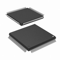
IC M16C MCU FLASH 256K 100LQFP
Manufacturer
Renesas Electronics America
Series
M16C™ M16C/60r
Datasheet
1.M30620FCNGPU5.pdf
(250 pages)
Specifications of M30624FGNGP#D5
Core Processor
M16C/60
Core Size
16-Bit
Speed
16MHz
Connectivity
SIO, UART/USART
Peripherals
DMA, PWM, WDT
Number Of I /o
85
Program Memory Size
256KB (256K x 8)
Program Memory Type
FLASH
Ram Size
20K x 8
Voltage - Supply (vcc/vdd)
3 V ~ 3.6 V
Data Converters
A/D 18x10b, D/A 2x8b
Oscillator Type
Internal
Operating Temperature
-20°C ~ 85°C
Package / Case
100-LQFP
Lead Free Status / RoHS Status
Contains lead / RoHS non-compliant
Eeprom Size
-
Available stocks
Company
Part Number
Manufacturer
Quantity
Price


Status Transition of BCLK
Status Transition of BCLK
Table 1.11.4. Operating modes dictated by settings of system clock control registers 0 and 1
CM1i : bit i of the address 0007
CM0i : bit i of the address 0006
Power dissipation can be reduced and low-voltage operation achieved by changing the count source for
BCLK. Table 1.11.4 shows the operating modes corresponding to the settings of system clock control
registers 0 and 1.
When reset, the device starts in division by 8 mode. The main clock division select bit 0 (bit 6 at address
0006
from high-speed/medium-speed mode to stop mode, shifting to low power dissipation mode and at a reset.
When shifting from high-speed/medium-speed mode to low-speed mode, the value before high-speed/
medium-speed mode is retained. The following shows the operational modes of BCLK.
(1) Division by 2 mode
(2) Division by 4 mode
(3) Division by 8 mode
(4) Division by 16 mode
(5) No-division mode
(6) Low-speed mode
(7) Low power dissipation mode
Note : Before the count source for BCLK can be changed from X
Invalid
Invalid
Invalid
CM17
The main clock is divided by 2 to obtain the BCLK.
The main clock is divided by 4 to obtain the BCLK.
The main clock is divided by 8 to obtain the BCLK. When reset, the device starts operating from this
mode. Before the user can go from this mode to no division mode, division by 2 mode, or division by 4
mode, the main clock must be oscillating stably. When going to low-speed or lower power consumption
mode, make sure the sub-clock is oscillating stably.
The main clock is divided by 16 to obtain the BCLK.
The main clock is divided by 1 to obtain the BCLK.
f
transferring from this mode to another or vice versa. At least 2 to 3 seconds are required after the sub-
clock starts. Therefore, the program must be written to wait until this clock has stabilized immediately
after powering up and after stop mode is cancelled.
f
C
C
0
1
1
0
is used as the BCLK. Note that oscillation of both the main and sub-clocks must have stabilized before
is the BCLK and the main clock is stopped.
16
the count source is going to be switched must be oscillating stably. Allow a wait time in software for
the oscillation to stabilize before switching over the clock.
) and the X
Invalid
Invalid
Invalid
CM16
1
0
1
0
IN
-X
OUT
CM07
drive capacity select bit (bit 5 at address 0007
0
0
0
0
0
1
1
16
16
Invalid
Invalid
CM06
0
0
1
0
0
CM05
0
0
0
0
0
0
1
Invalid
Invalid
Invalid
Invalid
Invalid
CM04
SINGLE-CHIP 16-BIT CMOS MICROCOMPUTER
IN
1
1
to X
CIN
Division by 2 mode
Division by 4 mode
Division by 8 mode
Division by 16 mode
No-division mode
Low-speed mode
Low power dissipation mode
or vice versa, the clock to which
16
) change to “1” when shifting
Operating mode of BCLK
M16C / 62N Group
Mitsubishi microcomputers
45
Related parts for M30624FGNGP#D5
Image
Part Number
Description
Manufacturer
Datasheet
Request
R

Part Number:
Description:
KIT STARTER FOR M16C/29
Manufacturer:
Renesas Electronics America
Datasheet:

Part Number:
Description:
KIT STARTER FOR R8C/2D
Manufacturer:
Renesas Electronics America
Datasheet:

Part Number:
Description:
R0K33062P STARTER KIT
Manufacturer:
Renesas Electronics America
Datasheet:

Part Number:
Description:
KIT STARTER FOR R8C/23 E8A
Manufacturer:
Renesas Electronics America
Datasheet:

Part Number:
Description:
KIT STARTER FOR R8C/25
Manufacturer:
Renesas Electronics America
Datasheet:

Part Number:
Description:
KIT STARTER H8S2456 SHARPE DSPLY
Manufacturer:
Renesas Electronics America
Datasheet:

Part Number:
Description:
KIT STARTER FOR R8C38C
Manufacturer:
Renesas Electronics America
Datasheet:

Part Number:
Description:
KIT STARTER FOR R8C35C
Manufacturer:
Renesas Electronics America
Datasheet:

Part Number:
Description:
KIT STARTER FOR R8CL3AC+LCD APPS
Manufacturer:
Renesas Electronics America
Datasheet:
Part Number:
Description:
KIT STARTER FOR RX610
Manufacturer:
Renesas Electronics America
Datasheet:

Part Number:
Description:
KIT STARTER FOR R32C/118
Manufacturer:
Renesas Electronics America
Datasheet:

Part Number:
Description:
KIT DEV RSK-R8C/26-29
Manufacturer:
Renesas Electronics America
Datasheet:

Part Number:
Description:
KIT STARTER FOR SH7124
Manufacturer:
Renesas Electronics America
Datasheet:

Part Number:
Description:
KIT STARTER FOR H8SX/1622
Manufacturer:
Renesas Electronics America
Datasheet:

Part Number:
Description:
KIT DEV FOR SH7203
Manufacturer:
Renesas Electronics America
Datasheet: