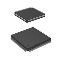
HD6417750RF240DV Renesas Electronics America, HD6417750RF240DV Datasheet - Page 979

HD6417750RF240DV
Manufacturer Part Number
HD6417750RF240DV
Description
MPU 3V 16K I-TEMP,PB-FREE 208-QF
Manufacturer
Renesas Electronics America
Series
SuperH® SH7750r
Datasheet
1.D6417750RBP240DV.pdf
(1164 pages)
Specifications of HD6417750RF240DV
Core Processor
SH-4
Core Size
32-Bit
Speed
240MHz
Connectivity
EBI/EMI, FIFO, SCI, SmartCard
Peripherals
DMA, POR, WDT
Number Of I /o
28
Program Memory Type
ROMless
Ram Size
48K x 8
Voltage - Supply (vcc/vdd)
1.4 V ~ 1.6 V
Oscillator Type
External
Operating Temperature
-40°C ~ 85°C
Package / Case
208-QFP
Lead Free Status / RoHS Status
Lead free / RoHS Compliant
Eeprom Size
-
Program Memory Size
-
Data Converters
-
Available stocks
Company
Part Number
Manufacturer
Quantity
Price
Company:
Part Number:
HD6417750RF240DV
Manufacturer:
HITACHI
Quantity:
7 287
- Current page: 979 of 1164
- Download datasheet (7Mb)
except by the following operations: update in the Update-IR state, initialization in the Test-Logic-
Reset state, and initialization by assertion of TRST.
21.3.4
In the SH7750R, setting a command from the H-UDI in SDIR can place the H-UDI pins in the
boundary scan mode. However, the following limitations apply.
1. Boundary scan does not cover clock-related signals (EXTAL, EXTAL2, XTAL, XTAL2, and
2. Boundary scan does not cover reset-related signals (RESET, CA)
3. Boundary scan does not cover H-UDI-related signals (TCK, TDI, TDO, TMS, TRST).
4. With EXTEST, assert the MRESET pin (low), the RESET pin (low), and CA pin (high). With
5. To perform boundary scan, supply a clock to the EXTAL pin, and wait for the power-on
21.4
1. SDIR Command
2. SDIR Commands in Sleep Mode
3. In standby mode, the H-UDI function cannot be used. Furthermore, TCK must be retained at a
4. The H-UDI is used for emulator connection. Therefore, H-UDI functions cannot be used when
5. The H-UDI pins of the SH7750 and SH7750S must not be connected to a boundary-scan signal
CKIO).
SAMPLE/PRELOAD, assert the CA pin (high).
oscillation settling time to elapse before starting boundary scan. The frequency range of the
input clock is from 1 to 33.3 MHz.
Note that after the power-on oscillation settling time has elapsed, a clock does not need to be
supplied to the EXTAL pin any longer.
For details on the power-on oscillation settling time, see section 22, Electrical Characteristics.
Once an SDIR command has been set, it remains unchanged until initialization by asserting
TRST or placing the TAP in the Test-Logic-Reset state, or until another command (other than
an H-UDI interrupt command) is written from the H-UDI.
Sleep mode is cleared by an H-UDI interrupt or H-UDI reset, and these exception requests are
accepted in this mode. In standby mode, neither an H-UDI interrupt nor an H-UDI reset is
accepted.
high level when entering the standby mode in order to retain the TAP state before and after
standby mode.
an emulator is used.
loop on the board.
Boundary Scan (EXTEST, SAMPLE/PRELOAD, BYPASS) (SH7750R Only)
Usage Notes
Section 21 High-performance User Debug Interface (H-UDI)
Rev.7.00 Oct. 10, 2008 Page 893 of 1074
REJ09B0366-0700
Related parts for HD6417750RF240DV
Image
Part Number
Description
Manufacturer
Datasheet
Request
R

Part Number:
Description:
KIT STARTER FOR M16C/29
Manufacturer:
Renesas Electronics America
Datasheet:

Part Number:
Description:
KIT STARTER FOR R8C/2D
Manufacturer:
Renesas Electronics America
Datasheet:

Part Number:
Description:
R0K33062P STARTER KIT
Manufacturer:
Renesas Electronics America
Datasheet:

Part Number:
Description:
KIT STARTER FOR R8C/23 E8A
Manufacturer:
Renesas Electronics America
Datasheet:

Part Number:
Description:
KIT STARTER FOR R8C/25
Manufacturer:
Renesas Electronics America
Datasheet:

Part Number:
Description:
KIT STARTER H8S2456 SHARPE DSPLY
Manufacturer:
Renesas Electronics America
Datasheet:

Part Number:
Description:
KIT STARTER FOR R8C38C
Manufacturer:
Renesas Electronics America
Datasheet:

Part Number:
Description:
KIT STARTER FOR R8C35C
Manufacturer:
Renesas Electronics America
Datasheet:

Part Number:
Description:
KIT STARTER FOR R8CL3AC+LCD APPS
Manufacturer:
Renesas Electronics America
Datasheet:

Part Number:
Description:
KIT STARTER FOR RX610
Manufacturer:
Renesas Electronics America
Datasheet:

Part Number:
Description:
KIT STARTER FOR R32C/118
Manufacturer:
Renesas Electronics America
Datasheet:

Part Number:
Description:
KIT DEV RSK-R8C/26-29
Manufacturer:
Renesas Electronics America
Datasheet:

Part Number:
Description:
KIT STARTER FOR SH7124
Manufacturer:
Renesas Electronics America
Datasheet:

Part Number:
Description:
KIT STARTER FOR H8SX/1622
Manufacturer:
Renesas Electronics America
Datasheet:

Part Number:
Description:
KIT DEV FOR SH7203
Manufacturer:
Renesas Electronics America
Datasheet:


