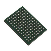
VSC8211XVW Vitesse Semiconductor Corp, VSC8211XVW Datasheet - Page 110

VSC8211XVW
Manufacturer Part Number
VSC8211XVW
Description
IC PHY 10/100/1000 SGL 117-LBGA
Manufacturer
Vitesse Semiconductor Corp
Type
PHY Transceiverr
Specifications of VSC8211XVW
Number Of Drivers/receivers
1/1
Protocol
Gigabit Ethernet
Voltage - Supply
3 V ~ 3.6 V
Mounting Type
Surface Mount
Package / Case
117-LBGA
Case
BGA
Dc
07+
Lead Free Status / RoHS Status
Lead free / RoHS Compliant
Other names
907-1023
Available stocks
Company
Part Number
Manufacturer
Quantity
Price
Company:
Part Number:
VSC8211XVW
Manufacturer:
VITESSE
Quantity:
5
Company:
Part Number:
VSC8211XVW
Manufacturer:
Semtech
Quantity:
3 413
Company:
Part Number:
VSC8211XVW
Manufacturer:
VITESSE
Quantity:
648
Company:
Part Number:
VSC8211XVW
Manufacturer:
Vitesse Semiconductor Corporation
Quantity:
10 000
Part Number:
VSC8211XVW
Manufacturer:
VITESSE
Quantity:
20 000
VSC8211
Datasheet
values are provided to compensate for PCB trace skews. The default values of these bits are specified by the RGMII Skew bits
in the CMODE hardware configuration. See Table 27,
“PHY Operating Condition Parameter Description,”
on page 68 for more
information.
23.7 – EWRAP Enable
When bit 23.7 is set to “1” and the MAC interface is set to TBI, data loopback is enabled on the MAC interface.
23.6 – TBI Bit Order Reversal Enable
Bit 23.6 allows the user to specify the bit order for the PCS when TBI mode is selected. By default, TBI bit order reversal, as
defined in the IEEE standard, is disabled.
23.5 – RX Idle Clock Enable
When bit 23.5 is set to “1”, a 25MHz clock is enabled on the RXCLK pin when the VSC8211 is in Enhanced ActiPHY mode.
When bit 23.5 is cleared, the RXCLK pin remains low during Enhanced ActiPHY mode. This clock is enabled by default.
23.4 – Register View
When bit 23.4 is set to “1”, MII registers 0:15 correspond to the definition in IEEE802.3 clause 28.2.4 (copper media). When bit
23.4 is cleared, MII registers 0:15 correspond to the definition in IEEE802.3 clause 37.2.5 (fiber media). Bit 23.4 is set to “1” by
default. Refer to
Section 25.1: "Clause 28/37 Resister View"
on page 82 for more information.
1
23.3 – Far End (Media-Side) Loopback Enable
When bit 23.3 is set to “1”, all incoming data from the link partner on the current media interface is retransmitted back to the link
partner on the media interface. In addition, the incoming data will also appear on the RX pins of the MAC interface. Any data
present on the TX pins of the MAC interface is ignored by the VSC8211 when bit 23.3 is set. In order to avoid loss of data, bit
23.3 should not be set while the VSC8211 is receiving data on the media interface. Bit 23.3 applies to all operating modes of the
VSC8211. When bit 23.3 is cleared, the VSC8211 resumes normal operation. This bit is cleared by default. Refer to
section 18.3, “Far-end Loopback,”
page 64.
23.0 – EEPROM Status
When bit 23.0 is set to “1”, an EEPROM has been detected on the external EEPROM interface. When cleared, bit 23.0 indicates
that no EEPROM has been detected.
1
This feature is not available in ‘TBI to CAT5 Media’ PHY operating mode.
110 of 165
VMDS-10105 Revision 4.1
October 2006


