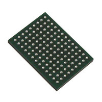
VSC8211XVW Vitesse Semiconductor Corp, VSC8211XVW Datasheet - Page 33

VSC8211XVW
Manufacturer Part Number
VSC8211XVW
Description
IC PHY 10/100/1000 SGL 117-LBGA
Manufacturer
Vitesse Semiconductor Corp
Type
PHY Transceiverr
Specifications of VSC8211XVW
Number Of Drivers/receivers
1/1
Protocol
Gigabit Ethernet
Voltage - Supply
3 V ~ 3.6 V
Mounting Type
Surface Mount
Package / Case
117-LBGA
Case
BGA
Dc
07+
Lead Free Status / RoHS Status
Lead free / RoHS Compliant
Other names
907-1023
Available stocks
Company
Part Number
Manufacturer
Quantity
Price
Company:
Part Number:
VSC8211XVW
Manufacturer:
VITESSE
Quantity:
5
Company:
Part Number:
VSC8211XVW
Manufacturer:
Semtech
Quantity:
3 413
Company:
Part Number:
VSC8211XVW
Manufacturer:
VITESSE
Quantity:
648
Company:
Part Number:
VSC8211XVW
Manufacturer:
Vitesse Semiconductor Corporation
Quantity:
10 000
Part Number:
VSC8211XVW
Manufacturer:
VITESSE
Quantity:
20 000
9.4.11 Twisted Pair Interface Signals
VMDS-10105 Revision 4.1
October 2006
LBGA
BALL
H13
H12
G13
G12
F13
F12
117
J13
J12
TXVNA
TXVNB
TXVPC
TXVNC
TXVPD
TXVND
TXVPA
TXVPB
Signal
Name
A
A
A
A
A
A
A
A
Type
DIFF
DIFF
DIFF
DIFF
DIFF
DIFF
DIFF
DIFF
TX/RX Channel “A” Positive Signal.
Positive differential signal connected to the positive primary side of the transformer. This
signal forms the positive signal of the “A” data channel. In 10/100/1000Mbps mode, this
signal generates the secondary side signal, normally connected to RJ-45 pin 1. In
100BASE-FX mode, it is connected instead to the positive SFP transmit data signal
(SFP_TD+). See
TX/RX Channel “A” Negative Signal.
Negative differential signal connected to the negative primary side of the transformer. This
signal forms the negative signal of the “A” data channel. In 10/100/1000Mbps mode, this
signal generates the secondary side signal, normally connected to RJ-45 pin 1. In
100BASE-FX mode, it is connected instead to the negative SFP transmit data signal
(SFP_TD–). See
TX/RX Channel “B” Positive Signal.
Positive differential signal connected to the positive primary side of the transformer. This
signal forms the positive signal of the “B” data channel. In 10/100/1000Mbps mode, this
signal generates the secondary side signal, normally connected to RJ-45 pin 1. In
100BASE-FX mode, it is connected instead to the positive SFP receive data signal
(SFP_RD+). See
TX/RX Channel “B” Negative Signal.
Negative differential signal connected to the negative primary side of the transformer. This
signal forms the negative signal of the “B” data channel. In 10/100/1000Mbps mode, this
signal generates the secondary side signal, normally connected to RJ-45 pin 1. In
100BASE-FX mode, it is connected instead to the negative SFP receive data signal
(SFP_RD–). See
TX/RX Channel “C” Positive Signal.
Positive differential signal connected to the positive primary side of the transformer. This
signals forms the positive signal of the “C” data. In 1000Mb mode, this signal generates
the secondary side signal, normally connected to RJ-45 pin 4 (not used in 10M/100M
modes). See
TX/RX Channel “C” Negative Signal.
Negative differential signal connected to the negative primary side of the transformer. This
signal forms the negative signal of the “C” data channel. In 1000Mb mode, this signal gen-
erates the secondary side signal, normally connected to RJ-45 pin 5 (not used in 10M/
100M modes). See
TX/RX Channel “D” Positive Signal.
Positive differential signal connected to the positive primary side of the transformer. This
signal forms the positive signal of the “D” data channel. In 1000Mb mode, this signal gen-
erates the secondary side signal, normally connected to RJ-45 pin 7 (not used in 10M/
100M modes). See
TX/RX Channel “D” Negative Signal.
Negative differential signal connected to the negative primary side of the transformer. This
signal forms the positive signal of the “D” data channel. In 1000Mb mode, this signal gen-
erates the secondary side signal, normally connected to RJ-45 pin 8 (not used in 10M/
100M modes). See
Table 12. Twisted Pair Interface Signals
Section 10: "System Schematics"
Section 10: "System Schematics"
Section 10: "System Schematics"
Section 10: "System Schematics"
Section 10: "System Schematics"
Section 10: “System Schematics”
Section 10: “System Schematics”
Section 10: “System Schematics”
33 of 165
Description
for details.
for details.
for details.
for details.
for details.
for details.
for details.
for details.
Datasheet
VSC8211


