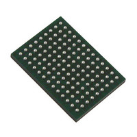
VSC8211XVW Vitesse Semiconductor Corp, VSC8211XVW Datasheet - Page 25

VSC8211XVW
Manufacturer Part Number
VSC8211XVW
Description
IC PHY 10/100/1000 SGL 117-LBGA
Manufacturer
Vitesse Semiconductor Corp
Type
PHY Transceiverr
Specifications of VSC8211XVW
Number Of Drivers/receivers
1/1
Protocol
Gigabit Ethernet
Voltage - Supply
3 V ~ 3.6 V
Mounting Type
Surface Mount
Package / Case
117-LBGA
Case
BGA
Dc
07+
Lead Free Status / RoHS Status
Lead free / RoHS Compliant
Other names
907-1023
Available stocks
Company
Part Number
Manufacturer
Quantity
Price
Company:
Part Number:
VSC8211XVW
Manufacturer:
VITESSE
Quantity:
5
Company:
Part Number:
VSC8211XVW
Manufacturer:
Semtech
Quantity:
3 413
Company:
Part Number:
VSC8211XVW
Manufacturer:
VITESSE
Quantity:
648
Company:
Part Number:
VSC8211XVW
Manufacturer:
Vitesse Semiconductor Corporation
Quantity:
10 000
Part Number:
VSC8211XVW
Manufacturer:
VITESSE
Quantity:
20 000
9.4.6 EEPROM Interface Signals
9.4.7 LED Interface Signals
VMDS-10105 Revision 4.1
October 2006
117 LBGA
117 LBGA
BALL
BALL
C13
C12
B13
B12
A13
H5
J5
Signal Name
Signal Name
PLLMODE
EECLK/
LED4
LED3
LED2
LED1
LED0
EEDAT
O
O
Type
O
Type
ZC
ZC
ZC
/I
/I
PD
PD
LED - Direct-Drive LED Outputs.
After reset, these pins serve as the direct drive, low EMI, LED driver output pins.
All LEDs are active-low and driven at a 3.3V logic-high through the VDD33A ana-
log power supply. The function of each LED can be set using hardware configura-
tion or via MII Register 27. Refer to
CMODE Pins”
Table 7. EEPROM Interface Signals
EECLK - EEPROM Clock Output.
This output is the clock line of the two-wire, MSA compliant serial EEPROM Inter-
face. This should be connected to the SCL input pin of the AT24 series of Atmel
EEPROMs. Refer
PLLMODE - PLL Mode Select Input.
PLLMODE is sampled during the device power-up sequence or on reset. When
PLLMODE is high, the PHY expects a 125MHz clock input as the PHY's reference
clock.
When low (default), a reference clock of 25MHz is expected at the REFCLK pin
from either an external crystal or a clock reference. This pin is internally pulled
down with a 100kΩ resistor.
EEPROM Serial I/O Data.
This bidirectional signal is the data line of the two wire, MSA compliant, serial
EEPROM Interface. This should be connected to the SDA pin of the AT24 series
of Atmel EEPROMs. Refer to
The PHY determines that an external EEPROM is present by monitoring the
EEDAT pin at power-up or when RESET is de-asserted. If EEDAT has a 4.7kΩ -
10kΩ external pull-up (to VDDIOMICRO) resistor, it assumes an EEPROM is
present. The EEDAT pin can be left floating or grounded to indicate no EEPROM.
Table 8. LED Interface Signals
and
25 of 165
Section 20: “EEPROM Interface”
MII Register 27
Section 20: “EEPROM Interface”
Description
for details.
Description
Section 19: “Hardware Configuration Using
for details.
for details.
Datasheet
VSC8211


