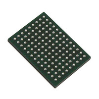
VSC8211XVW Vitesse Semiconductor Corp, VSC8211XVW Datasheet - Page 12

VSC8211XVW
Manufacturer Part Number
VSC8211XVW
Description
IC PHY 10/100/1000 SGL 117-LBGA
Manufacturer
Vitesse Semiconductor Corp
Type
PHY Transceiverr
Specifications of VSC8211XVW
Number Of Drivers/receivers
1/1
Protocol
Gigabit Ethernet
Voltage - Supply
3 V ~ 3.6 V
Mounting Type
Surface Mount
Package / Case
117-LBGA
Case
BGA
Dc
07+
Lead Free Status / RoHS Status
Lead free / RoHS Compliant
Other names
907-1023
Available stocks
Company
Part Number
Manufacturer
Quantity
Price
Company:
Part Number:
VSC8211XVW
Manufacturer:
VITESSE
Quantity:
5
Company:
Part Number:
VSC8211XVW
Manufacturer:
Semtech
Quantity:
3 413
Company:
Part Number:
VSC8211XVW
Manufacturer:
VITESSE
Quantity:
648
Company:
Part Number:
VSC8211XVW
Manufacturer:
Vitesse Semiconductor Corporation
Quantity:
10 000
Part Number:
VSC8211XVW
Manufacturer:
VITESSE
Quantity:
20 000
VSC8211
Datasheet
Tables
Table 1. Signal Type Description ......................................................................................................................... 20
Table 2. Configuration and Control Signals ......................................................................................................... 21
Table 3. System Clock Interface Signals (SCI) .................................................................................................... 22
Table 4. Analog Bias Signals ............................................................................................................................... 23
Table 5. JTAG Access Port .................................................................................................................................. 23
Table 6. Serial Management Interface Signals .................................................................................................... 24
Table 7. EEPROM Interface Signals ................................................................................................................... 25
Table 8. LED Interface Signals ............................................................................................................................ 25
Table 9. Parallel MAC Interface Signals - Transmit Signals ................................................................................ 26
Table 10. Parallel MAC Interface Signals - Receive Signals ................................................................................. 28
Table 11. Serial MAC/Media Interface Signals ...................................................................................................... 30
Table 12. Twisted Pair Interface Signals ............................................................................................................... 33
Table 13. Power Supply and Ground Connections ................................................................................................ 34
Table 14. No Connects .......................................................................................................................................... 34
Table 15. Power Supply and Associated Functional Signals ................................................................................. 35
Table 16. Accepted MDI Pair Connection Combinations ....................................................................................... 44
Table 17. SMI Pin Descriptions - MSA Mode ........................................................................................................ 46
Table 18. SMI Pin Descriptions - MSA Mode ........................................................................................................ 52
Table 19. SMI Frame Format ................................................................................................................................. 52
Table 20. LED Function Assignments .................................................................................................................... 54
Table 21. Parallel LED Functions .......................................................................................................................... 54
Table 22. LED Output Options ............................................................................................................................... 56
Table 23. JTAG Device Identification Register Description ................................................................................... 58
Table 24. JTAG Interface Instruction Codes .......................................................................................................... 58
Table 25. CMODE Pull-up/Pull-down Resistor Values ........................................................................................... 66
Table 26. CMODE Bit to PHY Operation Condition Parameter Mapping .............................................................. 67
Table 27. PHY Operating Condition Parameter Description .................................................................................. 68
Table 28. Configuration EEPROM Data Format .................................................................................................... 73
Table 29. PHY Operating Modes ........................................................................................................................... 76
Table 30. Clause 28 Register View Remote Fault Transmitted to Link Partner ..................................................... 78
Table 31. Clause 37 Register View Remote Fault Transmitted to Link Partner ..................................................... 78
Table 32. Clause 28 Autonegotiation Link Partner Remote Fault .......................................................................... 78
Table 33. Clause 37 Autonegotiation Link Partner Remote Fault .......................................................................... 79
Table 34. PHY Register Names and Addresses .................................................................................................... 83
Table 35. Bit Sequences for Generating Quinary Symbols ................................................................................... 97
Table 36. PHY Operating Modes ......................................................................................................................... 109
Table 37. Absolute Maximum Ratings ................................................................................................................. 133
Table 38. Recommended Operating Conditions .................................................................................................. 134
Table 39. PCB and Environmental Conditions ..................................................................................................... 135
Table 40. Thermal Resistance Data .................................................................................................................... 135
12 of 165
VMDS-10105 Revision 4.1
October 2006


