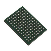
VSC8211XVW Vitesse Semiconductor Corp, VSC8211XVW Datasheet - Page 72

VSC8211XVW
Manufacturer Part Number
VSC8211XVW
Description
IC PHY 10/100/1000 SGL 117-LBGA
Manufacturer
Vitesse Semiconductor Corp
Type
PHY Transceiverr
Specifications of VSC8211XVW
Number Of Drivers/receivers
1/1
Protocol
Gigabit Ethernet
Voltage - Supply
3 V ~ 3.6 V
Mounting Type
Surface Mount
Package / Case
117-LBGA
Case
BGA
Dc
07+
Lead Free Status / RoHS Status
Lead free / RoHS Compliant
Other names
907-1023
Available stocks
Company
Part Number
Manufacturer
Quantity
Price
Company:
Part Number:
VSC8211XVW
Manufacturer:
VITESSE
Quantity:
5
Company:
Part Number:
VSC8211XVW
Manufacturer:
Semtech
Quantity:
3 413
Company:
Part Number:
VSC8211XVW
Manufacturer:
VITESSE
Quantity:
648
Company:
Part Number:
VSC8211XVW
Manufacturer:
Vitesse Semiconductor Corporation
Quantity:
10 000
Part Number:
VSC8211XVW
Manufacturer:
VITESSE
Quantity:
20 000
20 EEPROM Interface
The EEPROM Interface consists of the EEDAT and EECLK pins of the PHY. If this interface is used, these pins should connect
to the SDA and SCL pins respectively of a serial EEPROM that is compatible with the AT24xxx series of ATMEL EEPROMs.
The EEPROM interface on the VSC8211 serves the following purposes:
The PHY detects the EEPROM based on the presence of a pull-up on the EEDAT pin. It is initialized using the configuration
EEPROM (if present) under the following conditions:
If an EEPROM is present, the start-up control block looks for a “Vitesse Header” (value:16’hBDBD’) at addresses 0 and 1 of the
EEPROM. The address is incremented by 256 until the Vitesse Header is found. If the Vitesse Header is not found, or no
EEPROM is connected, the VSC8211 bypasses the EEPROM read step.
Once the Vitesse header is located, the EEPROM Interface block of the PHY searches for its PHY address in bit position 7:3 in
the subsequent EEPROM locations. Once the PHY address is located, the 11 bit EEPROM address location for the start of the
configuration script is read. At this point, the PHY begins reading from this 11 bit EEPROM address and initializes its Register
values based on the EEPROM configuration script contents. For more information see Table 28, “Configuration EEPROM Data
Format,” on page 73.
The total number of EEPROM bytes needed for a configuration script is equal to:
((Number of Register writes) * 3 + 2 (BDBD) + 2 (PHY address and Configuration Script Address) + 2 (Length of configuration
script)).
Data is read from the EEPROM sequentially (at 50 Khz, or 50 kbits/s) until all PHY Register are set. Once all of the PHY
registers are set, the PHY enters the ‘NORMAL STATE’
If the PHY is in ‘NORMAL STATE’ state, the user can access the EEPROM connected to the EEPROM interface through the
SMI. If the SMI is in IEEE mode, the EEPROM can be accessed via the SMI using
SMI is in MSA mode, the EEPROM can be accessed directly via the SMI i.e. the PHY behaves as if the MODDEF2 and
MODDEEF1 pins of the SMI are directly connected to the EEDAT and EECLK pins of the PHY.
One exception is the memory portion with device/page address ‘110’. This is reserved for the PHY Register access when the
PHY’s SMI is set in MSA mode.
If an EEPROM is present, but the EEPROM does not acknowledge (according to the ATMEL EEPROM protocol), the VSC8211
waits for an acknowledge for approximately 3 seconds. If there is no acknowledge within 3 seconds, the VSC8211 will abort and
continue into normal operation.
1
VMDS-10105 Revision 4.1
October 2006
EEPROM memory with device address ‘110’ cannot be accessed directly when the SMI is in MSA mode. This device address is reserved for
PHY Register access in MSA mode. To access EEPROM with device address ‘110’ in MSA mode
should be used.
• It provides the PHY with the ability to self configure its internal registers.
• The system manager can access the EEPROM to obtain information pertaining to the system/module
configuration.
• A single EEPROM can be shared among multiple PHYs for their custom configuration.
• RESET deassertion.
• TXDIS/SRESET deassertion and
• S/W reset (MII Register 0.15) is asserted and
Extended MII Register 21E.14
(Section 21: "PHY Startup and
72 of 165
Extended MII Register 21E.14
is set.
Extended MII Registers 21E and
Initialization").
Extended MII Registers 21E and 22E
is set.
1
Datasheet
VSC8211
22E. If the


