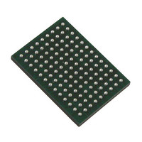
VSC8211XVW Vitesse Semiconductor Corp, VSC8211XVW Datasheet - Page 46

VSC8211XVW
Manufacturer Part Number
VSC8211XVW
Description
IC PHY 10/100/1000 SGL 117-LBGA
Manufacturer
Vitesse Semiconductor Corp
Type
PHY Transceiverr
Specifications of VSC8211XVW
Number Of Drivers/receivers
1/1
Protocol
Gigabit Ethernet
Voltage - Supply
3 V ~ 3.6 V
Mounting Type
Surface Mount
Package / Case
117-LBGA
Case
BGA
Dc
07+
Lead Free Status / RoHS Status
Lead free / RoHS Compliant
Other names
907-1023
Available stocks
Company
Part Number
Manufacturer
Quantity
Price
Company:
Part Number:
VSC8211XVW
Manufacturer:
VITESSE
Quantity:
5
Company:
Part Number:
VSC8211XVW
Manufacturer:
Semtech
Quantity:
3 413
Company:
Part Number:
VSC8211XVW
Manufacturer:
VITESSE
Quantity:
648
Company:
Part Number:
VSC8211XVW
Manufacturer:
Vitesse Semiconductor Corporation
Quantity:
10 000
Part Number:
VSC8211XVW
Manufacturer:
VITESSE
Quantity:
20 000
The MODDEF1/MDC, MODDEF2/MDIO, and the MDINT pins comprise the SMI interface.
By writing to
"EEPROM Interface"
13.1 PHY Register Access with SMI in MSA mode
In this mode, the PHY registers are accessed using the standard MSA compliant protocol. This protocol is generally used for
reading and writing to Atmel’s AT24 series compatible EEPROMs.
In this mode, the SMI pins function as follows:
According to the protocol described in the MSA specification, the following conditions are defined:
VMDS-10105 Revision 4.1
October 2006
1.
2.
• Start [S]: A high to low transition on the MODDEF2 pin when MODDEF1 is high.
• Data [D]: A transition on the MODDEF2 pin when MODDEF1 is low. A low to high transition is '1' and a
high to low transition is '0'.
• Stop [T]: A low to high transition on the MODDEF2 pin when MODDEF1 is high.
• Acknowledge (By Receiver) [A]: A low driven by the PHY/Receiver after 8 Data states. The transition on
MODDEF2 takes place when MODDEF1 is low. The host does not drive the MODDEF2 Data line in this
condition.
• Acknowledge (By Host) [H]: A low driven by the host after 8 Data states. The transition on MODDEF2
takes place when MODDEF1 is low. The PHY/Receiver does not drive the MODDEF2 Data line in this
condition.
• No Acknowledge (By Host) [N]: A high driven by the host after 8 Data states. The transition on
MODDEF2 takes place when MODDEF1 is low. The PHY/Receiver does not drive the MODDEF2 Data line
in this condition.
Pin Name
MODDEF1
MODDEF2
MDINT
MSA
IEEE
MII Register 21E.15
for details), the SMI of the PHY can be set to operate in one of the following two modes:
MODDEF2
MODDEF1
at startup (Refer to
Description
Clock Input. Connect to the SCL pin of the AT24 series of EEPROMs.
Bidirectional Data. Connect to the SDA pin of the AT24 series of EEPROMs. This
pin should be pulled high on the board using a 4.7kΩ to 10kΩ pull-up resistor.
Interrupt Signal.
Table 17. SMI Pin Descriptions - MSA Mode
Figure 16. Data Validity
Section 19: "Hardware Configuration Using CMODE Pins"
Data Stable
46 of 165
Change
Data
Data Stable
and
Datasheet
Section 20:
VSC8211


