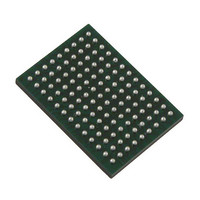
VSC8211XVW Vitesse Semiconductor Corp, VSC8211XVW Datasheet - Page 24

VSC8211XVW
Manufacturer Part Number
VSC8211XVW
Description
IC PHY 10/100/1000 SGL 117-LBGA
Manufacturer
Vitesse Semiconductor Corp
Type
PHY Transceiverr
Specifications of VSC8211XVW
Number Of Drivers/receivers
1/1
Protocol
Gigabit Ethernet
Voltage - Supply
3 V ~ 3.6 V
Mounting Type
Surface Mount
Package / Case
117-LBGA
Case
BGA
Dc
07+
Lead Free Status / RoHS Status
Lead free / RoHS Compliant
Other names
907-1023
Available stocks
Company
Part Number
Manufacturer
Quantity
Price
Company:
Part Number:
VSC8211XVW
Manufacturer:
VITESSE
Quantity:
5
Company:
Part Number:
VSC8211XVW
Manufacturer:
Semtech
Quantity:
3 413
Company:
Part Number:
VSC8211XVW
Manufacturer:
VITESSE
Quantity:
648
Company:
Part Number:
VSC8211XVW
Manufacturer:
Vitesse Semiconductor Corporation
Quantity:
10 000
Part Number:
VSC8211XVW
Manufacturer:
VITESSE
Quantity:
20 000
9.4.5 Serial Management Interface Signals
VMDS-10105 Revision 4.1
October 2006
117 LBGA
BALL
G4
H3
H4
Signal Name
MODDEF1/
MODDEF2/
MDINT
MDIO
MDC
Type
OD
I/O
I
Table 6. Serial Management Interface Signals
The Functionality of this pin is determined by the value of Extended
21E.15
the
MODDEF1 - Serial MSA Clock (valid in SFP Mode, when
= 1).
MODDEF1 is the clock input of the two-wire serial interface for accessing the
PHY’s registers or the EEPROM connected to the EEPROM Interface using the
protocol specified in the MSA specification. Although typically operated at
100kHz, MODDEF1 can be operated at a maximum of 1MHz.
MDC - Management Data Clock (valid in IEEE Mode, when
21E.15
MDC is the clock input of the two wire serial interface for accessing the PHY’s reg-
isters or the EEPROM connected to the EEPROM Interface using the Serial Man-
agement Interface protocol specified in the IEEE 802.3 specification. This clock is
typically between 0 to 12.5MHz and is usually asynchronous with respect to the
PHY's transmit or receive clock.
The Functionality of this pin is determined by the value of Extended
21E.15
the
MODDEF2 - Serial I/O Data (valid in SFP Mode, when
1).
MODDEF2 is the data line of the two-wire serial interface for accessing the PHY’s
registers or the EEPROM connected to the EEPROM Interface using the protocol
specified in the MSA specification. This pin normally requires a 1.5kΩ to 4.7kΩ
pull-up resistor to VDDIOMICRO at the Station Manager. The value of the pull-up
resistor depends on the MODDEF1 frequency and the capacitive load on the
MODDEF2 line.
MDIO - Serial I/OP Data (valid in IEEE Mode, when
MDIO is the data line of the two-wire serial interface for accessing the PHY’s reg-
isters or the EEPROM connected to the EEPROM Interface using the Serial Man-
agement Interface protocol specified in the IEEE 802.3 specification. This pin
normally requires a 1.5kΩ to 4.7kΩ pull-up resistor to VDDIOMICRO at the Station
Manager. The value of the pull-up resistor depends on the MDC frequency and
the capacitive load on the MDIO line.
Management Data Interrupt.
MDINT is asserted whenever there is a change in operating status of the device.
This open drain signal indicates a change in the PHY's link operating conditions
for which a Station Manager must interrogate to determine further information.
See
The assertion polarity of the MDINT is determined by the presence of a pull-up or
pull-down on the MDINT pin.
If the MDINT pin is pulled up to VDDIOMICRO using a 4.7kΩ το 10kΩ resistor, is
becomes an active low signal.
If the MDINT pin is pulled down using a 4.7kΩ το 10kΩ resistor, then it becomes
an active high signal.
EEPROM
EEPROM
MII Register 25
‘SFP MODE’ set at startup using CMODE Hardware Configuration or via
= 0).
‘SFP MODE’ set at startup using CMODE Hardware Configuration or via
interface.
interface.
24 of 165
and
MII Register 26
Description
for more information.
MII Register 21E.15
MII Register 21E.15
MII Register 21E.15
MII Register
MII Register
MII Register
Datasheet
VSC8211
= 0).
=


