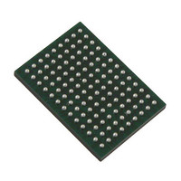
VSC8211XVW Vitesse Semiconductor Corp, VSC8211XVW Datasheet - Page 31

VSC8211XVW
Manufacturer Part Number
VSC8211XVW
Description
IC PHY 10/100/1000 SGL 117-LBGA
Manufacturer
Vitesse Semiconductor Corp
Type
PHY Transceiverr
Specifications of VSC8211XVW
Number Of Drivers/receivers
1/1
Protocol
Gigabit Ethernet
Voltage - Supply
3 V ~ 3.6 V
Mounting Type
Surface Mount
Package / Case
117-LBGA
Case
BGA
Dc
07+
Lead Free Status / RoHS Status
Lead free / RoHS Compliant
Other names
907-1023
Available stocks
Company
Part Number
Manufacturer
Quantity
Price
Company:
Part Number:
VSC8211XVW
Manufacturer:
VITESSE
Quantity:
5
Company:
Part Number:
VSC8211XVW
Manufacturer:
Semtech
Quantity:
3 413
Company:
Part Number:
VSC8211XVW
Manufacturer:
VITESSE
Quantity:
648
Company:
Part Number:
VSC8211XVW
Manufacturer:
Vitesse Semiconductor Corporation
Quantity:
10 000
Part Number:
VSC8211XVW
Manufacturer:
VITESSE
Quantity:
20 000
VMDS-10105 Revision 4.1
October 2006
LBGA
BALL
117
G2
G1
F2
F1
J1
J2
SCLKP
SCLKN
Signal
SDON
SDOP
Name
SDIP
SDIN
O
O
Type
I
DIFF
DIFF
DIFF
Table 11. Serial MAC/Media Interface Signals (continued)
SGMII Clock Differential Output Pair (used in SGMII to CAT5/SerDes/AMS PHY Oper-
ating Modes).
This signal pair is a differential 625MHz SGMII clock for the SGMII data in accordance
with Cisco’s SGMII specification. These pins should be AC-coupled with external 0.01μF
series capacitors or left unconnected when not used. See
ics”
see
Fiber Transceiver Differential Input Pair (used in SGMII to SerDes PHY Operating
Modes).
Differential 1.25Gbaud receiver inputs with register selectable on-chip 100Ω or 150Ω dif-
ferential termination. The SDIP and SDIN signals should be AC-coupled with external
0.01μF series capacitors. These signals usually connect to the RX signals of the Fiber
Optic Transceiver or the RX signals of a SerDes over the Backplane.
Fiber Transceiver Differential Output Pairs (used in SGMII to SerDes PHY Operating
Modes).
Differential 1.25Gbaud transmitter outputs. The SDOP and SDON signals should be AC-
coupled with external 0.01μF AC series capacitors, placed on the PHY side of these
traces. These signals usually connect to the TX signals of the Fiber Optic Transceiver or
the TX signals of a SerDes over the Backplane. The register selectable 100Ω or 150Ω dif-
ferential termination should be placed near the Transceiver/SerDes. For information about
adjusting the output swing of these pins, see
Register
for further information. For information about adjusting the output swing of these pins,
Register 17E (11h) – SerDes Control
#3, page 126.
31 of 165
Description
Register, page 124.
Register 20E (14h) – Extended PHY Control
Section 10: “System Schemat-
Datasheet
VSC8211


