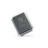
PI7C8140AMAE Pericom Semiconductor, PI7C8140AMAE Datasheet - Page 19

PI7C8140AMAE
Manufacturer Part Number
PI7C8140AMAE
Description
IC PCI-PCI BRIDGE 2PORT 128-QFP
Manufacturer
Pericom Semiconductor
Datasheet
1.PI7C8140AMAE.pdf
(82 pages)
Specifications of PI7C8140AMAE
Applications
*
Interface
*
Voltage - Supply
*
Package / Case
128-QFP
Mounting Type
Surface Mount
Maximum Operating Temperature
+ 85 C
Minimum Operating Temperature
0 C
Mounting Style
SMD/SMT
Operating Supply Voltage
3 V to 3.6 V
Supply Current (max)
230 mA
Lead Free Status / RoHS Status
Lead free / RoHS Compliant
Available stocks
Company
Part Number
Manufacturer
Quantity
Price
Company:
Part Number:
PI7C8140AMAE
Manufacturer:
Pericom
Quantity:
135
Company:
Part Number:
PI7C8140AMAE
Manufacturer:
SONY
Quantity:
469
Part Number:
PI7C8140AMAE
Manufacturer:
PERICOM
Quantity:
20 000
PI7C8140A
2-PORT PCI-TO-PCI BRIDGE
If offset 74h bits [8:7] = 00, the bridge converts Memory Write and Invalidate transactions to Memory
Write transactions at the destination.
If the value in the cache line size register does meet the memory write and invalidate conditions, the
bridge returns a target disconnect to the initiator on a cache line boundary.
2.5.3 DELAYED WRITE TRANSACTIONS
Delayed write forwarding is used for I/O write transactions and Type 1 configuration write transactions.
A delayed write transaction guarantees that the actual target response is returned back to the initiator
without holding the initiating bus in wait states. A delayed write transaction is limited to a single
DWORD data transfer.
When a write transaction is first detected on the initiator bus, and the bridge forwards it as a delayed
transaction, the bridge claims the access by asserting DEVSEL# and returns a target retry to the
initiator. During the address phase, the bridge samples the bus command, address, and address parity
one cycle later. After IRDY# is asserted, the bridge also samples the first data DWORD, byte enable
bits, and data parity. This information is placed into the delayed transaction queue. The transaction is
queued only if no other existing delayed transactions have the same address and command, and if the
delayed transaction queue is not full. When the delayed write transaction moves to the head of the
delayed transaction queue and all ordering constraints with posted data are satisfied. The bridge initiates
the transaction on the target bus. The bridge transfers the write data to the target. If the bridge receives
a target retry in response to the write transaction on the target bus, it continues to repeat the write
transaction until the data transfer is completed, or until an error condition is encountered.
24
32
If the bridge is unable to deliver write data after 2
(default) or 2
(maximum) attempts, the bridge will
report a system error. The bridge also asserts P_SERR# if the primary SERR# enable bit is set in the
command register. See Section 5.4 for information on the assertion of P_SERR#. When the initiator
repeats the same write transaction (same command, address, byte enable bits, and data), and the
completed delayed transaction is at the head of the queue, the bridge claims the access by asserting
DEVSEL# and returns TRDY# to the initiator, to indicate that the write data was transferred. If the
initiator requests multiple DWORD, the bridge also asserts STOP# in conjunction with TRDY# to
signal a target disconnect. Note that only those bytes of write data with valid byte enable bits are
compared. If any of the byte enable bits are turned off (driven HIGH), the corresponding byte of write
data is not compared.
If the initiator repeats the write transaction before the data has been transferred to the target, the bridge
returns a target retry to the initiator. The bridge continues to return a target retry to the initiator until
write data is delivered to the target, or until an error condition is encountered. When the write
transaction is repeated, the bridge does not make a new entry into the delayed transaction queue.
Section 2.8.3.1 provides detailed information about how the bridge responds to target termination
during delayed write transactions.
The bridge implements a discard timer that starts counting when the delayed write completion is at the
head of the delayed transaction completion queue. The initial value of this timer can be set to the retry
counter register offset 88h.
If the initiator does not repeat the delayed write transaction before the discard timer expires, the bridge
Page 19 of 82
March 20, 2007 – Revision 1.01
07-0067


