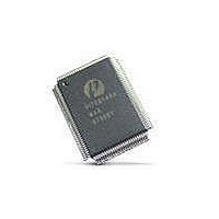
PI7C8140AMAE Pericom Semiconductor, PI7C8140AMAE Datasheet - Page 43

PI7C8140AMAE
Manufacturer Part Number
PI7C8140AMAE
Description
IC PCI-PCI BRIDGE 2PORT 128-QFP
Manufacturer
Pericom Semiconductor
Datasheet
1.PI7C8140AMAE.pdf
(82 pages)
Specifications of PI7C8140AMAE
Applications
*
Interface
*
Voltage - Supply
*
Package / Case
128-QFP
Mounting Type
Surface Mount
Maximum Operating Temperature
+ 85 C
Minimum Operating Temperature
0 C
Mounting Style
SMD/SMT
Operating Supply Voltage
3 V to 3.6 V
Supply Current (max)
230 mA
Lead Free Status / RoHS Status
Lead free / RoHS Compliant
Available stocks
Company
Part Number
Manufacturer
Quantity
Price
Company:
Part Number:
PI7C8140AMAE
Manufacturer:
Pericom
Quantity:
135
Company:
Part Number:
PI7C8140AMAE
Manufacturer:
SONY
Quantity:
469
Part Number:
PI7C8140AMAE
Manufacturer:
PERICOM
Quantity:
20 000
07-0067
5.2.3 DELAYED WRITE TRANSACTIONS
For upstream transactions, when the bridge detects a read data parity error on the primary bus, the
following events occur:
The bridge returns to the initiator the data and parity that was received from the target. When the
initiator detects a parity error on this read data and is enabled to report it, the initiator asserts PERR#
two cycles after the data transfer occurs. It is assumed that the initiator takes responsibility for handling
a parity error condition; therefore, when the bridge detects PERR# asserted while returning read data to
the initiator, the bridge does not take any further action and completes the transaction normally.
When the bridge detects a data parity error during a delayed write transaction, the initiator drives data
and data parity, and the target checks parity and conditionally asserts PERR#.
For delayed write transactions, a parity error can occur at the following times:
When a delayed write transaction is normally queued, the address, command, address parity, data, byte
enable bits, and data parity are all captured and a target retry is returned to the initiator. When the
bridge detects a parity error on the write data for the initial delayed write request transaction, the
following events occur:
Note: If parity checking is turned off and data parity errors have occurred for queued or subsequent
delayed write transactions on the initiator bus, it is possible that the initiator’s re-attempts of the write
transaction may not match the original queued delayed write information contained in the delayed
transaction queue. In this case, a master timeout condition may occur, possibly resulting in a system
error (P_SERR# assertion).
Bridge completes the transaction normally.
Bridge asserts P_PERR# two cycles following the data transfer, if the primary interface parity error
response bit is set in the command register.
Bridge sets the detected parity error bit in the primary status register.
Bridge sets the data parity detected bit in the primary status register, if the primary interface parity-
error-response bit is set in the command register.
Bridge forwards the bad parity with the data back to the initiator on the secondary bus. If the data
with the bad parity is pre-fetched and is not read by the initiator on the secondary bus, the data is
discarded and the data with bad parity is not returned to the initiator.
Bridge completes the transaction normally.
During the original delayed write request transaction
When the initiator repeats the delayed write request transaction
When the bridge completes the delayed write transaction to the target
If the parity-error-response bit corresponding to the initiator bus is set, the bridge asserts TRDY# to
the initiator and the transaction is not queued. If multiple data phases are requested, STOP# is also
asserted to cause a target disconnect. Two cycles after the data transfer, the bridge also asserts
PERR#.
If the parity-error-response bit is not set, the bridge returns a target retry. It queues the transaction
as usual. The bridge does not assert PERR#. In this case, the initiator repeats the transaction.
The bridge sets the detected-parity-error bit in the status register corresponding to the initiator bus,
regardless of the state of the parity-error-response bit.
Page 43 of 82
2-PORT PCI-TO-PCI BRIDGE
March 20, 2007 – Revision 1.01
PI7C8140A


