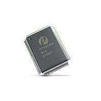
PI7C8140AMAE Pericom Semiconductor, PI7C8140AMAE Datasheet - Page 24

PI7C8140AMAE
Manufacturer Part Number
PI7C8140AMAE
Description
IC PCI-PCI BRIDGE 2PORT 128-QFP
Manufacturer
Pericom Semiconductor
Datasheet
1.PI7C8140AMAE.pdf
(82 pages)
Specifications of PI7C8140AMAE
Applications
*
Interface
*
Voltage - Supply
*
Package / Case
128-QFP
Mounting Type
Surface Mount
Maximum Operating Temperature
+ 85 C
Minimum Operating Temperature
0 C
Mounting Style
SMD/SMT
Operating Supply Voltage
3 V to 3.6 V
Supply Current (max)
230 mA
Lead Free Status / RoHS Status
Lead free / RoHS Compliant
Available stocks
Company
Part Number
Manufacturer
Quantity
Price
Company:
Part Number:
PI7C8140AMAE
Manufacturer:
Pericom
Quantity:
135
Company:
Part Number:
PI7C8140AMAE
Manufacturer:
SONY
Quantity:
469
Part Number:
PI7C8140AMAE
Manufacturer:
PERICOM
Quantity:
20 000
07-0067
2.6.8 FAST BACK-TO-BACK READ TRANSACTIONS
2.7
start the master timeout timer. The remaining read data will be discarded after the master timeout timer
expires. To provide better latency, if there are any other pending data for other transactions in the RDB
(Read Data Buffer), the remaining read data will be discarded even though the master timeout timer has
not expired.
The bridge implements a master timeout timer that starts counting when the delayed read completion is
at the head of the delayed transaction queue, and the read data is at the head of the read data queue. The
initial value of this timer is programmable through configuration register. If the initiator does not repeat
the read transaction and before the master timeout timer expires (2
read transaction and read data from its queues. The bridge also conditionally asserts P_SERR# (see
Section 5.4).
The bridge has the capability to post multiple delayed read requests, up to a maximum of four in each
direction. If an initiator starts a read transaction that matches the address and read command of a read
transaction that is already queued, the current read command is not posted as it is already contained in
the delayed transaction queue.
See Section 4 for a discussion of how delayed read transactions are ordered when crossing the bridge.
The bridge can recognize fast back-to-back read transactions.
CONFIGURATION TRANSACTIONS
Configuration transactions are used to initialize a PCI system. Every PCI device has a configuration
space that is accessed by configuration commands. All registers are accessible in configuration space
only.
In addition to accepting configuration transactions for initialization of its own configuration space, the
bridge also forwards configuration transactions for device initialization in hierarchical PCI systems, as
well as for special cycle generation.
To support hierarchical PCI bus systems, two types of configuration transactions are specified: Type 0
and Type 1.
Type 0 configuration transactions are issued when the intended target resides on the same PCI bus as
the initiator. A Type 0 configuration transaction is identified by the configuration command and the
lowest two bits of the address set to 00b.
Type 1 configuration transactions are issued when the intended target resides on another PCI bus, or
when a special cycle is to be generated on another PCI bus. A Type 1 configuration command is
identified by the configuration command and the lowest two address bits set to 01b.
The register number is found in both Type 0 and Type 1 formats and gives the DWORD address of the
configuration register to be accessed. The function number is also included in both Type 0 and Type 1
formats and indicates which function of a multifunction device is to be accessed. For single-function
devices, this value is not decoded. The addresses of Type 1 configuration transaction include a 5-bit
field designating the device number that identifies the device on the target PCI bus that is to be
Page 24 of 82
15
2-PORT PCI-TO-PCI BRIDGE
default), the bridge discards the
March 20, 2007 – Revision 1.01
PI7C8140A


