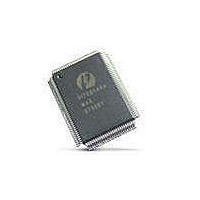
PI7C8140AMAE Pericom Semiconductor, PI7C8140AMAE Datasheet - Page 62

PI7C8140AMAE
Manufacturer Part Number
PI7C8140AMAE
Description
IC PCI-PCI BRIDGE 2PORT 128-QFP
Manufacturer
Pericom Semiconductor
Datasheet
1.PI7C8140AMAE.pdf
(82 pages)
Specifications of PI7C8140AMAE
Applications
*
Interface
*
Voltage - Supply
*
Package / Case
128-QFP
Mounting Type
Surface Mount
Maximum Operating Temperature
+ 85 C
Minimum Operating Temperature
0 C
Mounting Style
SMD/SMT
Operating Supply Voltage
3 V to 3.6 V
Supply Current (max)
230 mA
Lead Free Status / RoHS Status
Lead free / RoHS Compliant
Available stocks
Company
Part Number
Manufacturer
Quantity
Price
Company:
Part Number:
PI7C8140AMAE
Manufacturer:
Pericom
Quantity:
135
Company:
Part Number:
PI7C8140AMAE
Manufacturer:
SONY
Quantity:
469
Part Number:
PI7C8140AMAE
Manufacturer:
PERICOM
Quantity:
20 000
07-0067
13.2.5 REVISION ID REGISTER – OFFSET 08h
13.2.6 CLASS CODE REGISTER – OFFSET 08h
13.2.7 CACHE LINE REGISTER – OFFSET 0Ch
13.2.8 PRIMARY LATENCY TIMER REGISTER – OFFSET 0Ch
13.2.9 HEADER TYPE REGISTER – OFFSET 0Ch
13.2.10 PRIMARY BUS NUMBER REGISTER – OFFSET 18h
Bit
7:0
Bit
15:8
23:16
31:24
Bit
7:0
Bit
15:8
Bit
23:16
Bit
7:0
Function
Revision
Function
Programming
Interface
Sub-Class Code
Base Class
Code
Function
Cache Line
Size
Function
Primary
Latency timer
Function
Header Type
Function
Primary Bus
Number
Type
RO
Type
RO
RO
RO
Type
RW
Type
RW
Type
RO
Type
RW
Description
Indicates revision number of device. Hardwired to 00h
Description
Read as 00h to indicate no programming interfaces have been defined for PCI-to-
PCI bridges
Read as 04h to indicate device is PCI-to-PCI bridge
Read as 06h to indicate device is a bridge device
Description
Designates the cache line size for the system and is used when terminating
memory write and invalidate transactions and when prefetching memory read
transactions.
Only cache line sizes (in units of 4-byte) which are a power of two are valid (only
one bit can be set in this register; only 00h, 01h, 02h, 04h, 08h, and 10h are valid
values).
Reset to 0
Description
This register sets the value for the Master Latency Timer, which starts counting
when the master asserts FRAME#.
Reset to 0
Description
Read as 01h to indicate that the register layout conforms to the standard PCI-to-
PCI bridge layout.
Description
Indicates the number of the PCI bus to which the primary interface is connected.
The value is set in software during configuration.
Reset to 0
Page 62 of 82
2-PORT PCI-TO-PCI BRIDGE
March 20, 2007 – Revision 1.01
PI7C8140A


