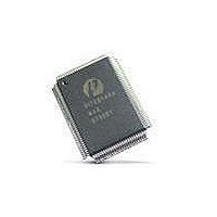
PI7C8140AMAE Pericom Semiconductor, PI7C8140AMAE Datasheet - Page 38

PI7C8140AMAE
Manufacturer Part Number
PI7C8140AMAE
Description
IC PCI-PCI BRIDGE 2PORT 128-QFP
Manufacturer
Pericom Semiconductor
Datasheet
1.PI7C8140AMAE.pdf
(82 pages)
Specifications of PI7C8140AMAE
Applications
*
Interface
*
Voltage - Supply
*
Package / Case
128-QFP
Mounting Type
Surface Mount
Maximum Operating Temperature
+ 85 C
Minimum Operating Temperature
0 C
Mounting Style
SMD/SMT
Operating Supply Voltage
3 V to 3.6 V
Supply Current (max)
230 mA
Lead Free Status / RoHS Status
Lead free / RoHS Compliant
Available stocks
Company
Part Number
Manufacturer
Quantity
Price
Company:
Part Number:
PI7C8140AMAE
Manufacturer:
Pericom
Quantity:
135
Company:
Part Number:
PI7C8140AMAE
Manufacturer:
SONY
Quantity:
469
Part Number:
PI7C8140AMAE
Manufacturer:
PERICOM
Quantity:
20 000
07-0067
3.4.2 VGA SNOOP MODE
4
4.1
The bridge provides VGA snoop mode, allowing for VGA palette write transactions to be forwarded
downstream. This mode is used when a graphics device downstream from the bridge needs to snoop or
respond to VGA palette write transactions. To enable the mode, set the VGA snoop bit in the command
register in configuration space. Note that the bridge claims VGA palette write transactions by asserting
DEVSEL# in VGA snoop mode.
When VGA snoop bit is set, the bridge forwards downstream transactions within the 3C6h, 3C8h and
3C9h I/O addresses space. Note that these addresses are also forwarded as part of the VGA
compatibility mode previously described. Again, address bits <15:10> are not decoded, while address
bits <31:16> must be equal to 0, which means that these addresses are aliases every 1KB throughout the
first 64KB of I/O space.
Note: If both the VGA mode bit and the VGA snoop bit are set, the bridge behaves in the same way as
if only the VGA mode bit were set.
TRANSACTION ORDERING
To maintain data coherency and consistency, the bridge complies with the ordering rules set forth in the
PCI Local Bus Specification, Revision 2.2, for transactions crossing the bridge. This chapter describes
the ordering rules that control transaction forwarding across the bridge.
TRANSACTIONS GOVERNED BY ORDERING RULES
Ordering relationships are established for the following classes of transactions crossing the bridge:
Posted write transactions, comprised of memory write and memory write and invalidate
transactions.
Posted write transactions complete at the source before they complete at the destination; that is, data is
written into intermediate data buffers before it reaches the target.
Delayed write request transactions, comprised of I/O write and configuration write transactions.
Delayed write requests are terminated by target retry on the initiator bus and are queued in the delayed
transaction queue. A delayed write transaction must complete on the target bus before it completes on
the initiator bus.
Delayed write completion transactions, comprised of I/O write and configuration write
transactions.
Delayed write completion transactions complete on the target bus, and the target response is queued in
the buffers. A delayed write completion transaction proceeds in the direction opposite that of the
original delayed write request; that is, a delayed write completion transaction proceeds from the target
bus to the initiator bus.
Delayed read request transactions, comprised of all memory read, I/O read, and configuration
read transactions.
Delayed read requests are terminated by target retry on the initiator bus and are queued in the delayed
transaction queue.
Page 38 of 82
2-PORT PCI-TO-PCI BRIDGE
March 20, 2007 – Revision 1.01
PI7C8140A


