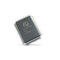
PI7C8140AMAE Pericom Semiconductor, PI7C8140AMAE Datasheet - Page 27

PI7C8140AMAE
Manufacturer Part Number
PI7C8140AMAE
Description
IC PCI-PCI BRIDGE 2PORT 128-QFP
Manufacturer
Pericom Semiconductor
Datasheet
1.PI7C8140AMAE.pdf
(82 pages)
Specifications of PI7C8140AMAE
Applications
*
Interface
*
Voltage - Supply
*
Package / Case
128-QFP
Mounting Type
Surface Mount
Maximum Operating Temperature
+ 85 C
Minimum Operating Temperature
0 C
Mounting Style
SMD/SMT
Operating Supply Voltage
3 V to 3.6 V
Supply Current (max)
230 mA
Lead Free Status / RoHS Status
Lead free / RoHS Compliant
Available stocks
Company
Part Number
Manufacturer
Quantity
Price
Company:
Part Number:
PI7C8140AMAE
Manufacturer:
Pericom
Quantity:
135
Company:
Part Number:
PI7C8140AMAE
Manufacturer:
SONY
Quantity:
469
Part Number:
PI7C8140AMAE
Manufacturer:
PERICOM
Quantity:
20 000
07-0067
2.7.4 SPECIAL CYCLES
2.8
The bridge also supports Type 1 to Type 1 forwarding of configuration write transactions upstream to
support upstream special cycle generation. A Type 1 configuration command is forwarded upstream
when the following conditions are met:
The bridge forwards Type 1 to Type 1 configuration write transactions as delayed transactions. Type 1
to Type 1 configuration write transactions are limited to a single data transfer.
The Type 1 configuration mechanism is used to generate special cycle transactions in hierarchical PCI
systems. Special cycle transactions are ignored by acting as a target and are not forwarded across the
bridge. Special cycle transactions can be generated from Type 1 configuration write transactions in
either the upstream or the down-stream direction.
The birdge initiates a special cycle on the target bus when a Type 1 configuration write transaction is
being detected on the initiating bus and the following conditions are met during the address phase:
When the bridge initiates the transaction on the target interface, the bus command is changed from
configuration write to special cycle. The address and data are for-warded unchanged. Devices that use
special cycles ignore the address and decode only the bus command. The data phase contains the special
cycle message. The transaction is forwarded as a delayed transaction, but in this case the target
response is not forwarded back (because special cycles result in a master abort). Once the transaction is
completed on the target bus, through detection of the master abort condition, the bridge responds with
TRDY# to the next attempt of the con-figuration transaction from the initiator. If more than one data
transfer is requested, the bridge responds with a target disconnect operation during the first data phase.
TRANSACTION TERMINATION
This section describes how bridge returns transaction termination conditions back to the initiator.
The initiator can terminate transactions with one of the following types of termination:
The bus command is a configuration read or write transaction.
The lowest two address bits are equal to 01b.
The bus number falls outside the range defined by the lower limit (inclusive) in the secondary bus
number register and the upper limit (inclusive) in the subordinate bus number register.
The device number in address bits AD[15:11] is equal to 11111b.
The function number in address bits AD[10:8] is equal to 111b.
The bus command is a configuration write transaction.
The lowest two address bits on AD[1:0] are equal to 01b.
The device number in address bits AD[15:11] is equal to 11111b.
The function number in address bits AD[10:8] is equal to 111b.
The register number in address bits AD[7:2] is equal to 000000b.
The bus number is equal to the value in the secondary bus number register in configuration space
for downstream forwarding or equal to the value in the primary bus number register in
configuration space for upstream forwarding.
The bus command on CBE# is a configuration write command.
Page 27 of 82
2-PORT PCI-TO-PCI BRIDGE
March 20, 2007 – Revision 1.01
PI7C8140A


