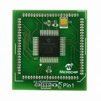
MA180023 Microchip Technology, MA180023 Datasheet - Page 238

MA180023
Manufacturer Part Number
MA180023
Description
MODULE PLUG-IN PIC18F46J11 PIM
Manufacturer
Microchip Technology
Series
PIC®r
Datasheet
1.MA180023.pdf
(528 pages)
Specifications of MA180023
Accessory Type
Plug-In Module (PIM) - PIC18F46J11
Tool / Board Applications
General Purpose MCU, MPU, DSP, DSC
Mcu Supported Families
PIC18
Supported Devices
Stand-alone Or W/ HPC(DM183022) Or PIC18(DM183032)
Silicon Manufacturer
Microchip
Core Architecture
PIC
Core Sub-architecture
PIC18
Silicon Core Number
PIC18F
Silicon Family Name
PIC18FxxJxx
Lead Free Status / RoHS Status
Lead free / RoHS Compliant
For Use With/related Products
HPC Explorer Board (DM183022) or PIC18 Explorer Board (DM183032)
For Use With
DM183032 - BOARD EXPLORER PICDEM PIC18DM183022 - BOARD DEMO PIC18FXX22 64/80TQFP
Lead Free Status / RoHS Status
Lead free / RoHS Compliant
Available stocks
Company
Part Number
Manufacturer
Quantity
Price
Company:
Part Number:
MA180023
Manufacturer:
Microchip Technology
Quantity:
135
- Current page: 238 of 528
- Download datasheet (8Mb)
PIC18F46J11 FAMILY
When ALRMCFG = 00 and the CHIME bit = 0
(ALRMCFG<6>), the repeat function is disabled and
only a single alarm will occur. The alarm can be
repeated up to 255 times by loading the ALRMRPT
register with FFh.
After each alarm is issued, the ALRMRPT register is
decremented by one. Once the register has reached
‘00’, the alarm will be issued one last time.
After the alarm is issued a last time, the ALRMEN bit is
cleared automatically and the alarm turned off. Indefinite
repetition of the alarm can occur if the CHIME bit = 1.
When CHIME = 1, the alarm is not disabled when the
ALRMRPT register reaches ‘00’, but it rolls over to FF
and continues counting indefinitely.
FIGURE 16-6:
16.4
The timer and alarm can optionally continue to operate
while in Sleep, Idle and even Deep Sleep mode. An
alarm event can be used to wake-up the microcontroller
from any of these Low-Power modes.
16.5
16.5.1
When a device Reset occurs, the ALCFGRPT register
is forced to its Reset state causing the alarm to be dis-
abled (if enabled prior to the Reset). If the RTCC was
enabled, it will continue to operate when a basic device
Reset occurs.
DS39932C-page 238
RTCC Alarm Event
Low-Power Modes
Reset
ALRMEN bit
DEVICE RESET
RTCEN bit
RTCC Pin
TIMER PULSE GENERATION
16.3.2
At every alarm event, an interrupt is generated. Addi-
tionally, an alarm pulse output is provided that operates
at half the frequency of the alarm.
The alarm pulse output is completely synchronous with
the RTCC clock and can be used as a trigger clock to
other peripherals. This output is available on the RTCC
pin. The output pulse is a clock with a 50% duty cycle
and a frequency half that of the alarm event (see
Figure 16-6).
The RTCC pin also can output the seconds clock. The
user can select between the alarm pulse, generated by
the RTCC module, or the seconds clock output.
The RTSECSEL (PADCFG1<1:0>) bits select between
these two outputs:
• Alarm pulse – RTSECSEL<1:0> = 00
• Seconds clock – RTSECSEL<1:0> = 0
16.5.2
The RTCCFG and ALRMRPT registers are reset only
on a POR. Once the device exits the POR state, the
clock registers should be reloaded with the desired
values.
The timer prescaler values can be reset only by writing
to the SECONDS register. No device Reset can affect
the prescalers.
ALARM INTERRUPT
POWER-ON RESET (POR)
© 2009 Microchip Technology Inc.
Related parts for MA180023
Image
Part Number
Description
Manufacturer
Datasheet
Request
R

Part Number:
Description:
Manufacturer:
Microchip Technology Inc.
Datasheet:

Part Number:
Description:
Manufacturer:
Microchip Technology Inc.
Datasheet:

Part Number:
Description:
Manufacturer:
Microchip Technology Inc.
Datasheet:

Part Number:
Description:
Manufacturer:
Microchip Technology Inc.
Datasheet:

Part Number:
Description:
Manufacturer:
Microchip Technology Inc.
Datasheet:

Part Number:
Description:
Manufacturer:
Microchip Technology Inc.
Datasheet:

Part Number:
Description:
Manufacturer:
Microchip Technology Inc.
Datasheet:

Part Number:
Description:
Manufacturer:
Microchip Technology Inc.
Datasheet:


