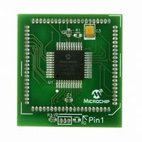
MA180023 Microchip Technology, MA180023 Datasheet - Page 481

MA180023
Manufacturer Part Number
MA180023
Description
MODULE PLUG-IN PIC18F46J11 PIM
Manufacturer
Microchip Technology
Series
PIC®r
Datasheet
1.MA180023.pdf
(528 pages)
Specifications of MA180023
Accessory Type
Plug-In Module (PIM) - PIC18F46J11
Tool / Board Applications
General Purpose MCU, MPU, DSP, DSC
Mcu Supported Families
PIC18
Supported Devices
Stand-alone Or W/ HPC(DM183022) Or PIC18(DM183032)
Silicon Manufacturer
Microchip
Core Architecture
PIC
Core Sub-architecture
PIC18
Silicon Core Number
PIC18F
Silicon Family Name
PIC18FxxJxx
Lead Free Status / RoHS Status
Lead free / RoHS Compliant
For Use With/related Products
HPC Explorer Board (DM183022) or PIC18 Explorer Board (DM183032)
For Use With
DM183032 - BOARD EXPLORER PICDEM PIC18DM183022 - BOARD DEMO PIC18FXX22 64/80TQFP
Lead Free Status / RoHS Status
Lead free / RoHS Compliant
Available stocks
Company
Part Number
Manufacturer
Quantity
Price
Company:
Part Number:
MA180023
Manufacturer:
Microchip Technology
Quantity:
135
- Current page: 481 of 528
- Download datasheet (8Mb)
TABLE 28-8:
TABLE 28-9:
TABLE 28-10: INTERNAL RC ACCURACY (INTOSC AND INTRC SOURCES)
© 2009 Microchip Technology Inc.
F10
F11
F12
1A
1
2
3
4
Note 1:
Note 1:
Param.
Param
Param
No.
No.
No.
† Data in “Typ” column is at 3.3V, 25°C, unless otherwise stated. These parameters are for design guidance
INTOSC Accuracy @ Freq = 8 MHz, 4 MHz, 2 MHz, 1 MHz, 500 kHz, 250 kHz, 125 kHz, 31 kHz
All Devices
INTRC Accuracy @ Freq = 31 kHz
All Devices
F
T
T
T
T
T
T
F
F
t
Symbol
rc
OSC
CY
OS
OS
OS
OS
Sym
OSC
PLLIN
PLLO
Instruction cycle period (T
except PLL. All specified values are based on characterization data for that particular oscillator type under
standard operating conditions with the device executing code. Exceeding these specified limits may result
in an unstable oscillator operation and/or higher than expected current consumption. All devices are tested
to operate at “min.” values with an external clock applied to the OSC1/CLKI pin. When an external clock
input is used, the “max.” cycle time limit is “DC” (no clock) for all devices.
only and are not tested.
The accuracy specification of the 31 kHz clock is determined by which source is providing it at a given time.
When INTSRC (OSCTUNE<7>) is ‘1’, use the INTOSC accuracy specification. When INTSRC is ‘0’, use
the INTRC accuracy specification.
L,
H
R,
F
PLL Input Frequency Range
PLL Output Frequency (4x F
PLL Start-up Time (lock time)
EXTERNAL CLOCK TIMING REQUIREMENTS
PLL CLOCK TIMING SPECIFICATIONS
Device
External CLKI Frequency
Oscillator Frequency
External CLKI Period
Oscillator Period
Instruction Cycle Time
External Clock in (OSC1)
High or Low Time
External Clock in (OSC1)
Rise or Fall Time
Characteristic
Characteristic
CY
20.3
(1)
Min
-1
-1
) equals four times the input oscillator time base period for all configurations
(1)
(1)
(1)
(1)
+/-0.15
+/-0.25
PLLIN
(1)
Typ
—
)
20.8
83.3
62.5
83.3
83.3
Min
DC
10
—
4
4
4
Max
42.2
+1
+1
PIC18F46J11 FAMILY
Units
kHz
Max
Min
%
%
250
250
DC
7.5
16
—
48
12
16
12
—
—
—
4
-40°C to +85°C
-40°C to +85°C
Units
Typ†
MHz
MHz
0°C to +85°C
ns
ns
ns
ns
ns
—
—
—
EC Oscillator mode
ECPLL Oscillator mode
HS Oscillator mode
HSPLL Oscillator mode
EC Oscillator mode
ECPLL Oscillator mode
HS Oscillator mode
HSPLL Oscillator mode
T
EC Oscillator mode
EC Oscillator mode
CY
Max
= 4/F
12
48
2
Conditions
OSC
Conditions
Units
V
V
MHz
MHz
, Industrial
ms
DDCORE
DDCORE
V
V
V
DS39932C-page 481
DD
DD
DD
= 2.0-3.6V,
= 2.0-3.6V,
= 2.0-3.3V
Conditions
(1)
= 2.0-2.7V
= 2.0-2.7V
Related parts for MA180023
Image
Part Number
Description
Manufacturer
Datasheet
Request
R

Part Number:
Description:
Manufacturer:
Microchip Technology Inc.
Datasheet:

Part Number:
Description:
Manufacturer:
Microchip Technology Inc.
Datasheet:

Part Number:
Description:
Manufacturer:
Microchip Technology Inc.
Datasheet:

Part Number:
Description:
Manufacturer:
Microchip Technology Inc.
Datasheet:

Part Number:
Description:
Manufacturer:
Microchip Technology Inc.
Datasheet:

Part Number:
Description:
Manufacturer:
Microchip Technology Inc.
Datasheet:

Part Number:
Description:
Manufacturer:
Microchip Technology Inc.
Datasheet:

Part Number:
Description:
Manufacturer:
Microchip Technology Inc.
Datasheet:


