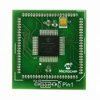
MA180023 Microchip Technology, MA180023 Datasheet - Page 51

MA180023
Manufacturer Part Number
MA180023
Description
MODULE PLUG-IN PIC18F46J11 PIM
Manufacturer
Microchip Technology
Series
PIC®r
Datasheet
1.MA180023.pdf
(528 pages)
Specifications of MA180023
Accessory Type
Plug-In Module (PIM) - PIC18F46J11
Tool / Board Applications
General Purpose MCU, MPU, DSP, DSC
Mcu Supported Families
PIC18
Supported Devices
Stand-alone Or W/ HPC(DM183022) Or PIC18(DM183032)
Silicon Manufacturer
Microchip
Core Architecture
PIC
Core Sub-architecture
PIC18
Silicon Core Number
PIC18F
Silicon Family Name
PIC18FxxJxx
Lead Free Status / RoHS Status
Lead free / RoHS Compliant
For Use With/related Products
HPC Explorer Board (DM183022) or PIC18 Explorer Board (DM183032)
For Use With
DM183032 - BOARD EXPLORER PICDEM PIC18DM183022 - BOARD DEMO PIC18FXX22 64/80TQFP
Lead Free Status / RoHS Status
Lead free / RoHS Compliant
Available stocks
Company
Part Number
Manufacturer
Quantity
Price
Company:
Part Number:
MA180023
Manufacturer:
Microchip Technology
Quantity:
135
- Current page: 51 of 528
- Download datasheet (8Mb)
3.6.7
This section gives the typical sequence for using the
Deep Sleep mode. Optional steps are indicated, and
additional information is given in notes at the end of the
procedure.
1.
2.
3.
4.
5.
6.
7.
8.
9.
10. If using an RTCC alarm for wake-up, wait until
11. Enter Deep Sleep mode by setting the DSEN bit
12. Once a wake-up event occurs, the device will
13. Determine if the device exited Deep Sleep by
14. Clear the Deep Sleep bit, DS (WDTCON<3>).
15. Determine the wake-up source by reading the
16. Determine if a DSBOR event occurred during
17. Read the DSGPR0 and DSGPR1 context save
18. Clear the RELEASE bit (DSCONL<0>).
© 2009 Microchip Technology Inc.
Note 1: DSWDT
Enable DSWDT (optional).
Configure DSWDT clock source (optional).
Enable DSBOR (optional).
Enable RTCC (optional).
Configure the RTCC peripheral (optional).
Configure the ULPWU peripheral (optional).
Enable the INT0 Interrupt (optional).
Context save SRAM data by writing to the
DSGPR0 and DSGPR1 registers (optional).
Set the REGSLP bit (WDTCON<7>) and clear
the IDLEN bit (OSCCON<7>).
the RTCSYNC (RTCCFG<4>) bit is clear.
(DSCONH<7>) and issuing a SLEEP instruction.
These two instructions must be executed back
to back.
perform a POR reset sequence. Code execution
resumes at the device’s Reset vector.
reading the Deep Sleep bit, DS (WDTCON<3>).
This bit will be set if there was an exit from Deep
Sleep mode.
DSWAKEH and DSWAKEL registers.
Deep Sleep mode by reading the DSBOR bit
(DSCONL<1>).
registers (optional).
2: The DSWDT and RTCC clock sources
3: For more information, see Section 16.0
4: For more information on configuring this
TYPICAL DEEP SLEEP SEQUENCE
through the devices’ Configuration bits.
For more information, see Section 25.1
“Configuration Bits”.
are selected through the devices’ Con-
figuration bits. For more information, see
Section 25.1 “Configuration Bits”.
“Real-Time
(RTCC)”.
peripheral,
Low-Power Wake-up”.
and
see
Clock
(3)
DSBOR
(1)
(1)
Section 3.7
and
are
(4)
Calendar
enabled
(3)
(2)
“Ultra
(4)
PIC18F46J11 FAMILY
3.6.8
If during Deep Sleep the device is subjected to unusual
operating conditions, such as an Electrostatic Dis-
charge (ESD) event, it is possible that the internal
circuit states used by the Deep Sleep module could
become corrupted. If this were to happen, the device
may exhibit unexpected behavior, such as a failure to
wake back up.
In order to prevent this type of scenario from occurring,
the
self-monitoring capability. During Deep Sleep, critical
internal nodes are continuously monitored in order to
detect possible Fault conditions (which would not
ordinarily occur). If a Fault condition is detected, the
circuitry will set the DSFLT status bit (DSWAKEL<7>)
and automatically wake the microcontroller from Deep
Sleep, causing a POR Reset.
During Deep Sleep, the Fault detection circuitry is
always enabled and does not require any specific
configuration prior to entering Deep Sleep.
Deep
DEEP SLEEP FAULT DETECTION
Sleep
module
includes
DS39932C-page 51
automatic
Related parts for MA180023
Image
Part Number
Description
Manufacturer
Datasheet
Request
R

Part Number:
Description:
Manufacturer:
Microchip Technology Inc.
Datasheet:

Part Number:
Description:
Manufacturer:
Microchip Technology Inc.
Datasheet:

Part Number:
Description:
Manufacturer:
Microchip Technology Inc.
Datasheet:

Part Number:
Description:
Manufacturer:
Microchip Technology Inc.
Datasheet:

Part Number:
Description:
Manufacturer:
Microchip Technology Inc.
Datasheet:

Part Number:
Description:
Manufacturer:
Microchip Technology Inc.
Datasheet:

Part Number:
Description:
Manufacturer:
Microchip Technology Inc.
Datasheet:

Part Number:
Description:
Manufacturer:
Microchip Technology Inc.
Datasheet:


