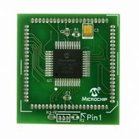
MA180023 Microchip Technology, MA180023 Datasheet - Page 55

MA180023
Manufacturer Part Number
MA180023
Description
MODULE PLUG-IN PIC18F46J11 PIM
Manufacturer
Microchip Technology
Series
PIC®r
Datasheet
1.MA180023.pdf
(528 pages)
Specifications of MA180023
Accessory Type
Plug-In Module (PIM) - PIC18F46J11
Tool / Board Applications
General Purpose MCU, MPU, DSP, DSC
Mcu Supported Families
PIC18
Supported Devices
Stand-alone Or W/ HPC(DM183022) Or PIC18(DM183032)
Silicon Manufacturer
Microchip
Core Architecture
PIC
Core Sub-architecture
PIC18
Silicon Core Number
PIC18F
Silicon Family Name
PIC18FxxJxx
Lead Free Status / RoHS Status
Lead free / RoHS Compliant
For Use With/related Products
HPC Explorer Board (DM183022) or PIC18 Explorer Board (DM183032)
For Use With
DM183032 - BOARD EXPLORER PICDEM PIC18DM183022 - BOARD DEMO PIC18FXX22 64/80TQFP
Lead Free Status / RoHS Status
Lead free / RoHS Compliant
Available stocks
Company
Part Number
Manufacturer
Quantity
Price
Company:
Part Number:
MA180023
Manufacturer:
Microchip Technology
Quantity:
135
- Current page: 55 of 528
- Download datasheet (8Mb)
3.7
The Ultra Low-Power Wake-up (ULPWU) on RA0 allows
a slow falling voltage to generate an interrupt without
excess current consumption.
Follow these steps to use this feature:
1.
2.
3.
4.
5.
6.
7.
8.
When the voltage on RA0 drops below V
will be generated, which will cause the device to
wake-up and execute the next instruction.
This feature provides a low-power technique for
periodically waking up the device from Sleep mode.
The time-out is dependent on the discharge time of the
RC circuit on RA0.
When the ULPWU module causes the device to
wake-up from Sleep mode, the WDTCON<ULPLVL>
bit is set. When the ULPWU module causes the device
to
(DSWAKEL<5>) bit is set. Software can check these
bits upon wake-up to determine the wake-up source.
Also in Sleep mode, only the remappable output func-
tion, ULPWU, will output this bit value to an RPn pin for
externally detecting wake-up events.
© 2009 Microchip Technology Inc.
Configure a remappable output pin to output the
ULPOUT signal.
Map an INTx interrupt-on-change input function
to the same pin as used for the ULPOUT output
function. Alternatively, in step 1, configure
ULPOUT
interrupt-on-change pin.
Charge the capacitor on RA0 by configuring the
RA0 pin to an output and setting it to ‘1’.
Enable interrupt for the corresponding pin
selected in step 2.
Stop charging the capacitor by configuring RA0
as an input.
Discharge the capacitor by setting the ULPEN
and ULPSINK bits in the WDTCON register.
Configure Sleep mode.
Enter Sleep mode.
wake-up
Ultra Low-Power Wake-up
from
to
output
Deep
Sleep,
onto
a
IL
the
, an interrupt
PORTB
DSULP
PIC18F46J11 FAMILY
See Example 3-1 for initializing the ULPWU module.
A series resistor between RA0 and the external
capacitor provides overcurrent protection for the
RA0/AN0/C1INA/ULPWU/RP0 pin and can allow for
software calibration of the time-out (see Figure 3-9).
FIGURE 3-9:
A timer can be used to measure the charge time and
discharge time of the capacitor. The charge time can
then be adjusted to provide the desired interrupt delay.
This technique will compensate for the affects of
temperature, voltage and component accuracy. The
peripheral can also be configured as a simple Program-
mable Low-Voltage Detect (LVD) or temperature
sensor.
Note:
Note:
For module-related bit definitions, see the
WDTCON
“Watchdog Timer (WDT)” and the
DSWAKEL register (Register 3-6).
RA0
For more information, refer to AN879,
“Using the Microchip Ultra Low-Power
Wake-up
(DS00879).
SERIAL RESISTOR
Module”
register
R
1
application
in
DS39932C-page 55
C
1
Section 25.2
note
Related parts for MA180023
Image
Part Number
Description
Manufacturer
Datasheet
Request
R

Part Number:
Description:
Manufacturer:
Microchip Technology Inc.
Datasheet:

Part Number:
Description:
Manufacturer:
Microchip Technology Inc.
Datasheet:

Part Number:
Description:
Manufacturer:
Microchip Technology Inc.
Datasheet:

Part Number:
Description:
Manufacturer:
Microchip Technology Inc.
Datasheet:

Part Number:
Description:
Manufacturer:
Microchip Technology Inc.
Datasheet:

Part Number:
Description:
Manufacturer:
Microchip Technology Inc.
Datasheet:

Part Number:
Description:
Manufacturer:
Microchip Technology Inc.
Datasheet:

Part Number:
Description:
Manufacturer:
Microchip Technology Inc.
Datasheet:


